It’s a simple fact that more wireless devices in the same space makes it more difficult to maintain reliable performance. More devices require finding more empty space in which to operate. And in this era of shrinking spectrum, empty space is at a premium and demand for wireless keeps climbing.
In addition, every time we turn on another transmitter, it increases the amount of intermodulation (IMD) in the workspace (Figure 1). Just so you don’t have to do the math – four transmitters deliver 24 IMD products, eight transmitters provide north of 40,000 products and by 16 transmitters the number goes beyond 20 trillion!
It’s a complex dance involving transmitter output power and relative distances between them. In practice, this typically just adds up to a rise in the noise floor.
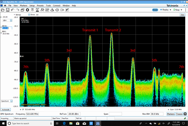
Another consideration is that for every 1 dB increase in the power of a transmitter, the 3rd-order IM increases by 3 dB. That’s a major reason when operating multiple transmitters to always use the minimum power necessary.
The general rule of thumb has always been that channels should be assigned a frequency at least 250 kHz away from any strong 3rd-order harmonic. The more space, the better.
Thankfully with the rise of software coordination programs, we no longer need to do the heavy lifting of calculating the intermodulation frequencies ourselves. I highly recommend taking advantage of these programs any time you’re using multiple wireless systems.
Ample Separation
The basic element of the strategy for spacing wireless microphone and in-ear monitoring systems is to operate the mics at one end of the band and the IEMs at the other end. Without getting overly complicated, a best practice is to group the mics together and group the IEMs together as tightly as possible with a gap between them of at least 4 MHz, but ideally much more.
Based on the most common blocks for wireless systems in the U.S., make certain all mic systems can tune below 558 MHz and all IEMs can tune above 564 MHz, although other split points can be used to match specific equipment.
The exact frequencies used will, of course, be determined by the local conditions at the venue and the total number of frequencies required. (And note that this practice can be flipped, with IEMs on the lower end and mics on the higher end.)
In addition, it’s best not to mix IEM frequencies between mic frequencies nor mics between IEM frequencies. If you’re dealing with you own gear, there may be no other choice but you’re not necessarily out of luck; however, maintaining reliable, dropout-free performance will likely be more difficult. Whatever the case, be sure to allow at least 4 MHz between the mic and IEM system ends.
Additional Help
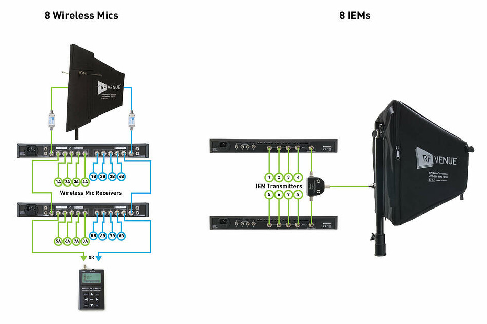
To further decouple the effect that IEM transmitters place on the mic receivers, simply add the appropriate pair of bandpass filters (BPFs) at the A and B antennas and connect into the antenna distribution system (Figure 2).
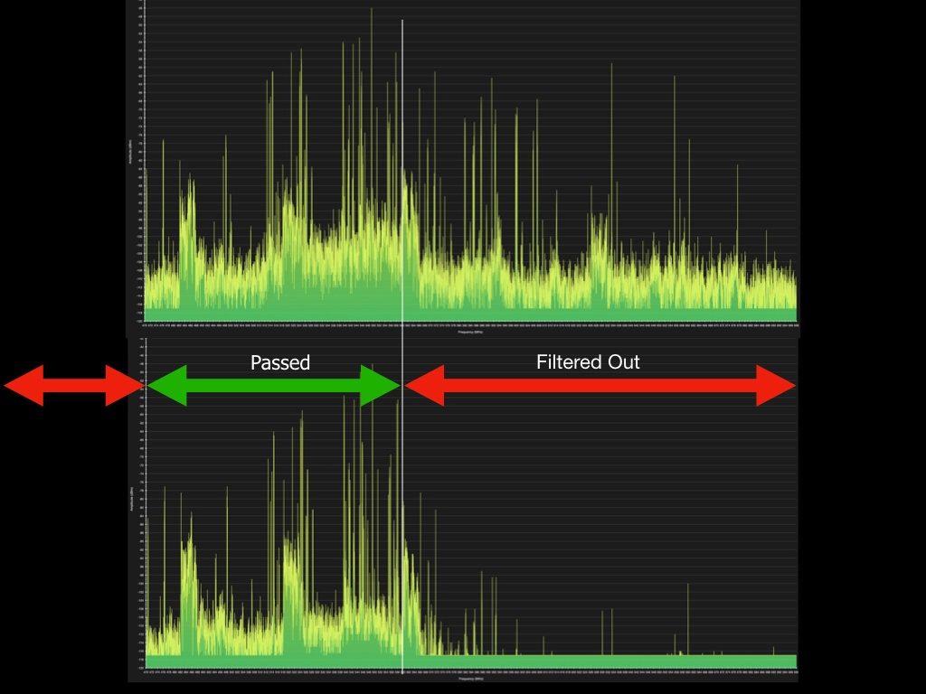
These filters allow the frequencies inside the bandpass to pass through unaffected but block RF from outside the bandpass (namely the signals from the IEMs) from ever getting into the mic receivers. The result is that as far as the mic receivers are concerned, the IEM signals don’t exist as they will be knocked down by about 40 dB.
Why not add BPFs to the IEMs, one might ask? The bandpass filters block RF from entering receivers, so it would be necessary to add a BPF to each and every IEM beltpack. Most performers would be greatly annoyed by the extra bulk, not to mention the expense! Because the transmission power from wireless mics is typically much lower than that from IEMs, our ears are not nearly as negatively affected by the mics as the mics are by the IEMs.
Note that when employing a pair of (RF Venue) DISTRO4 antenna distribution systems, any spare output can be utilized to connect to a spectrum analyzer to get an exact sense of whether IEM frequencies or IMD products are impacting the receivers (Figure 3).
If you encounter this on your scans, then the next step is a thorough “war gaming” exercise to root out the frequency (or multiple frequencies) causing the ingress to the mic system. Frequency coordination software tools are powerful but they’re no match for on-the-ground visual spot checking for noise entering the mic receivers.
By all means, the basic strategy presented here can be modified to be used with any different combination of wireless mics and IEMs (and IFBs – interrupt foldback systems). Certainly, there are more advanced techniques for larger scale projects.
Just remember to maintain a guard band of at least 4 MHz in the middle for good performance. And don’t forget to position transmitting and receiving antennas a minimum of 4 feet apart (further is better).
Get more details on this and related topics by downloading “Three Essential Concepts In Wireless Audio,” a free ebook available here.