Because the impedance of a loudspeaker is a frequency-dependent parameter, it must be measured at multiple frequencies to get a true picture of what the amplifier is “seeing” at its output terminals.
While very sophisticated methods and instruments exist, you can get a pretty good idea about the impedance curve of a loudspeaker with a standard real-time analyzer.
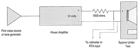
You will need a pink noise generator and voltage source of at least 10 volts RMS to drive the loudspeaker. A small power amplifier with at least a 12.5 watt rating into 8 ohms works well for this purpose.
1) Place a 1000 ohm resistor in series with the amplifier output.
This value will allow impedances up to 100 ohms to be measured (most loudspeakers).

2) With this configuration, the voltage across the load will be proportional to the impedance of the load.
The impedance measurement will be made by measuring the voltage across the load with a voltmeter or real-time analyzer.
3) To calibrate the setup, substitute an 8 ohm noninductive load resistor for the loudspeaker under test, and adjust the analyzer for a nominal reading.
This reading should be a flat line, and its position on the analyzer read out will correlate with an 8 ohm resistance.

4. Substitute the loudspeaker under test for the resistor. You will now be viewing the impedance curve of the loudspeaker.
Since the vertical markings are in dB, you must convert back to ohms to find the actual impedance at any specific frequency.
This method should serve to provide you with meaningful information about minimum impedances, box tunings, etc.
More comprehensive impedance measurement tools are available for those who need to measure Thiele-Small parameters, etc.
The plot in Figure 2 was made with “The Woofer Tester” from Peak Instruments Co., a dedicated impedance measurement system that requires a PC for operation. It measures the small signal parameters of raw loud speakers and vented boxes, including fs, Qts, Vas, BL, Le, fsb, and more.
The instrument can quickly measure a load impedance at up to 256 discrete frequencies and plot the response in graphical form. From such a graph the minimum impedance, loudspeaker free-air resonance, box tunings, etc. can be examined.

The software is a DOS application that runs on any PC with EGA graphics or higher and an available COM port. At S250, The Woofer Tester is the lowest price entry into high-resolution impedance measurements that I am aware of.
The ability to make high-resolution impedance measurements is quickly becoming a standard part of the system technician’s required capabilities. Impedance measurements can be used to quickly diagnose a number of problems which include amplifier overheating and box resonances.

Any of the current generation of real-time analyzers and PC-based measurement systems can, in theory, perform these measurements using the method described above. Those that need a faster, automated, and more cost effective approach might consider a dedicated impedance test system. Such a device can quickly and accurately measure the impedance of a raw loudspeaker or group of loudspeakers, and even determine the Thiele-Small parameters for a vented box design.


