Measurement Results
An Ear Simulator in any of these fixtures paired with a modern analyzer capable of Farina log-swept-sine chirps can provide a wide range of measurement results, including:
• Frequency Response
• Electrical Impedance
• Input Voltages
• Sound Pressure Level
• Harmonic and Intermodulation Distortion
• Noise Attenuation
• Crosstalk Attenuation
• Rub and Buzz
• Left/Right Tracking
The reflections from the pinnae and the impedance and resonances of the ear canal are faithfully modeled by the Ear Simulator and its microphone, providing the response curve at the DRP.
However, as seen in Figure 3, this raw measurement data does not easily correlate with published data, standards, or engineering specifications for the device under test that cite free field or diffuse field response curves. This can be accomplished by converting the measured data using free field or diffuse field Head Related Transfer Function (HRTF) curves.
An HRTF is created by first measuring the response curve of an Ear Simulator at DRP (in a HATS, for example), and then removing the HATS and placing a microphone at the same location, and measuring a second response curve.
These measurements can be made in either a free field (anechoic space) or diffuse field (reverberant space). The difference between the two measurements is the HRTF, plotting the characteristics of the acoustic test fixture being used.
Once the HTRF is obtained, the free field or diffuse field response of the headphone under test can be obtained by dividing the frequency response at the DRP by the appropriate HTRF.
Additional Factors
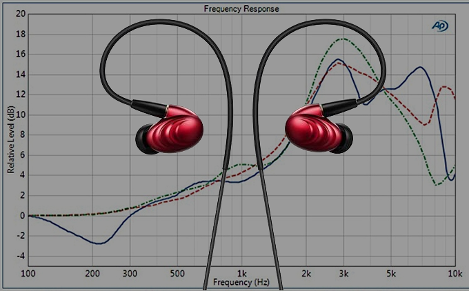
The fit of an earphone to the head and/or pinna can have a dramatic effect on performance. This is especially true for the bass response of closed headphones; leaks of any sort will reduce the ability to generate sufficient sound at low frequencies.
For example, Figure 8 shows five frequency response measurements, where the headphones were removed from the ATF and then reapplied before each measurement.

To account for this variation with fit, it is a good practice to average the results of several measurements (typically 3 to 5) with the headphones being removed and re-applied between measurements.
In the past, headphone target responses were designed to match the free-field HRTF for the position directly in front of the listener. Later, a diffuse field HRTF was added as an ideal for studio monitor headphones.
Recent work on this subject indicates that listeners prefer alternatives to the free field or diffuse field headphone target frequency response curves described here, and that in general, trained listeners preferred a headphone target response that corresponds to a flat loudspeaker calibrated in a reference listening room.