Parallel Splits
The simplest form of splitter is the parallel type split. This involves taking a mic cable and simply “Y” connecting the plus, minus and ground wires to two or three other cables.
Although this method successfully connects the mic to multiple mixing consoles, be aware that it connects the consoles directly to each other as well.
Most modern consoles will behave rather nicely configured this way but sometimes, mostly in older units, the consoles will interact with each other. This can happen when making adjustments at one console causes the electrical characteristics of its input circuitry to change.
These changes may reflect through a parallel split and possibly upset the input circuitry of the second console. For example, if adjusting the gain on console A causes the DC voltages of A’s input to change, this will show up at the input of console B. In some cases, this might cause the gain to change on console B, definitely a bad situation.
If you’re considering a parallel split, you can test for this by making up a microphone Y cable, attaching a mic to both consoles, and trying it out.
Make adjustments on each console, especially to the trim or gain section, while listening to the other. Turn the phantom power on and off each console. If you don’t notice any changes in volume or quality of sound, then a parallel split should work OK. (Adding the actual lengths of cable to each leg of the split can present other issues, such as added capacitance and increased susceptibility to RF interference.)
However, if the consoles are interacting, or if you are traveling and will be splitting to unfamiliar consoles regularly, then it would be wise to accomplish the split by using transformers.
Transformer Isolated Splits
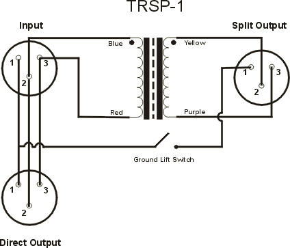
In a transformer splitter, the microphone is wired straight through to a “direct out” and also to the input of a splitting transformer. (See Figure 1 below.)
This transformer has a 1:1 turns ratio and its output side is connected to the second or “Isolated” split output. (Transformers with two or more secondaries are used for achieving more than one iso split.)
The transformer will pass the microphone’s AC audio signal but will block DC voltage in either direction. This helps prevent interaction between the consoles.
One of the outputs is usually wired as a direct connection because the transformer will also block phantom power (DC). Remember to plan on connecting this direct leg of the split to the console that will be providing the phantom power.
Another benefit of using a transformer split is that it increases each leg’s ability to reject interference by improving the “balanced” characteristic of the line (called “Common Mode Rejection” or CMR).
A disadvantage of this type of split is the added expense of the transformers. High quality transformers are essential for providing proper shielding and for preserving the frequency response of the mic signal – don’t cut corners here!

