Some audio professionals find power alleys, which are associated with left-right subwoofer deployments, objectionable. This is somewhat ironic considering that modern full-range loudspeakers also go down to 63 Hz (and lower).
And their bottom octaves are subject to the same artifacts when deployed left and right. Despite this, left-right mains are still the standard in typical PA systems and continue to be widely accepted.
Double standards set aside, if one insists on minimizing power alleys while sticking to left-right subwoofer deployment utilizing low-directional systems on each side, one can consider using signal post processing to minimize the interference patterns (spoiler alert: processing will come at a cost).
But first, let’s address the elephant in the room.
Root Cause
The root cause of power alleys is failure to steer the left and right subwoofers clear of each other’s territories when passing correlated signals. This means that both sides are stepping on each other’s turf.
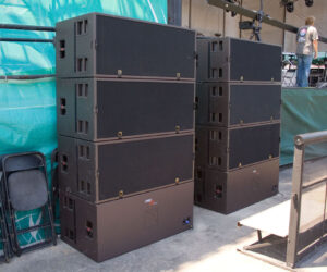
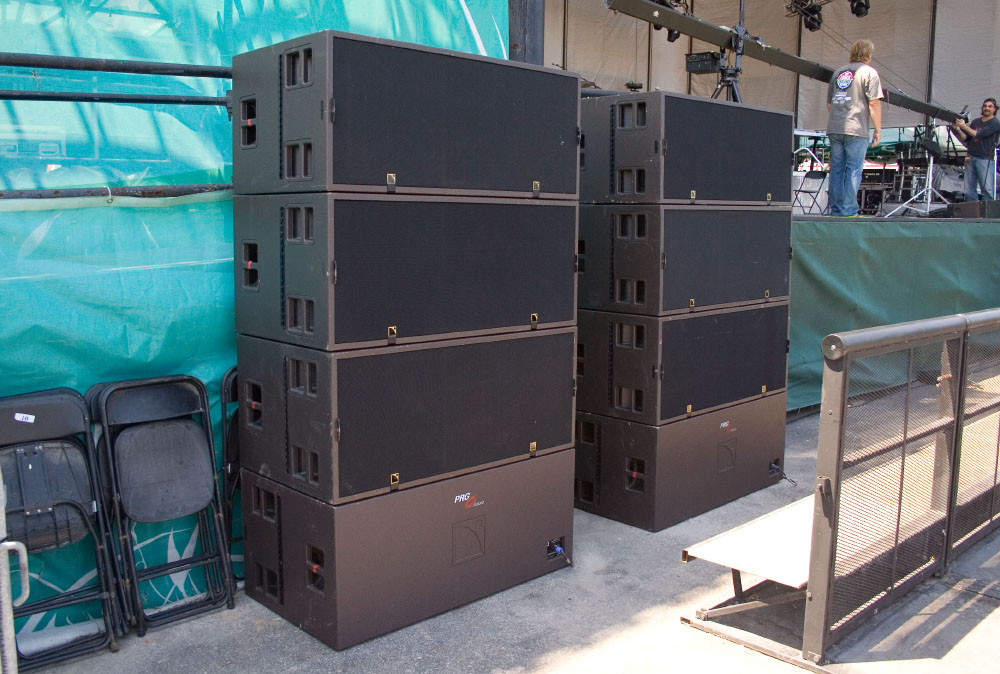
Typical subwoofers are effectively omnidirectional, which means they cannot be physically aimed to reduce overlap. Even entry-level cardioid solutions, which provide about 180 degrees of horizontal coverage, will still experience significant overlap unless both sides are angled outward.
When the audience majority hears identical signals at similar levels from both sides, physical displacement between the two sides creates time offsets that cause undesirable interference patterns. This affects all listeners except those near the median plane between both sides. To avoid power alleys, it’s necessary to divide either the audience area or the audio signals (de-correlation) by:
— Dividing the audience area. Prevent the crosstalk by using highly directional LF systems (narrow enough to stick to their respective audience halves) while only leaving a minor mold mark at the middle seam where left meets right.
— Dividing the audio signals. Prevent the interference by using de-correlated signals for each side that simply plow through each other (mixing as opposed to summing).
Neither approach will be explored in this article. Instead, we’re going to continue under the assumption of highly overlapped sides that pass identical signals, and resort to symptom/treatment (as opposed to symptom/ prevention) by virtue of signal post processing in an attempt to “redistribute the error.”
It shouldn’t come as a surprise this will come at a cost since the root cause is not addressed. However, let us outline the main idea first followed by two implementation methods.
Main Idea
The goal is to divide the subwoofer frequency band into to several fractional octaves and alternate them between left and right in a leapfrog fashion (Figure 1.1 and 1.3). This means that for each fractional octave, the audience is under the sole custody of either the left or right side as opposed to the shared custody of both sides.

The leapfrog order is intended to interweave both sides and maintain the illusion of sound coming from left and right. While specific implementation methods may vary, the general idea has been around for decades, is by no means novel, and is still being taught by a few loudspeaker manufacturers.
The principal impetus for writing this article is that the topic every now and then re-emerges on social media where it is mistaken for a “new shiny thing.” The fact that it is not widely spread knowledge is indicative of its limited success.
Example
Figure 2 shows an configuration with the subwoofers spaced 20 meters apart facing a 40 by 40 meter audience area. We will use two microphone positions to evaluate frequency responses (Figure 1) and impulse responses (Figure 7).

Method 1: Comb filters. This approach splits both left and right channels. Where for each channel, the copies are delayed – by the same amount – and then added back to their originals (Figure 3). It produces a harmonic series consisting of linear spaced alternating crests and troughs whose bandwidths decrease with increasing frequency. In addition, for — either — left or right, the delayed signal copy is polarity reversed prior to summing.

This results in one channel exhibiting a regular comb filter whereas the other channel now features a complementary – inverted – comb filter where the troughs have been turned into crests and vice versa (Figure 1.1). The amount of delay determines the density of crests and troughs, and thereby the number of alternations between both sides. Where more delay results in more frequent alternations in exchange for more time smearing.
Figure 4 shows a sound field comparison without and with processing (40 ms). Without processing, the disputed power alleys (and valleys) are readily apparent, whereas with processing, one can clearly see both sides take turns.

Please keep in mind that at the crossovers between consecutive crests (where the black and red traces in Figure 1.1 cross). Both sides once more run at the same level, and for those remaining frequencies (not shown in Figure 4), power alleys will occur as usual.
Method 2: EQ. This approach uses a series of very narrow parametric EQs that can be spaced logarithmically as well as linearly (Method 1), and where users can resort to just cuts or boosts as well.
Extreme EQ (Figure 5) is required to attempt to achieve the separation between both sides expected of Method 1 (Figure 1.1). Notice in Figure 1.3 that despite the drastic EQ, separation is not (and cannot be) as good as Method 1.

Figure 6 shows a sound field comparison without and with processing. While the results with processing are reminiscent of those shown in Figure 4, the poorer separation between sides results in more ripple over space – but clearly not as much as without any processing altogether.

How Does It Sound?
While all of this may look very promising, possibly even enticing. One should consider first what these approaches may sound like. Figure 7 shows impulse responses at both microphone positions (shown in Figure 2) for three scenarios: 1) no processing, 2) with comb filters, and 3) with EQ.

Without processing on-axis to the right subwoofer (Figure 7.2), the left subwoofer will be late by about 27 ms, causing some time smearing and tonal coloration. This is the usual cost of doing business for overlapping subwoofers deployed left and right while passing the same signal.
With comb filter processing, the fact that there is no change at FOH (Figure 7.3) deserves some explanation. If one carefully studies Figure 3, one should appreciate that in the absence of excess level and time offsets downstream, once sound is airborne (the natural condition at FOH when situated exactly in the middle between left and right). The delayed signal copies, due to the polarity reversal, completely cancel each other out, leaving only their unprocessed originals.
However, once you abandon the FOH position (Figure 7.4), those special conditions no longer apply, and you experience a compound of the artifacts also experienced at that position without processing (Figure 7.2) – whereas with EQ processing, both microphone positions exhibit significantly more sustain.
This should not come as a surprise. The very narrow PEQs with high Q values are very resonant. Making their center frequencies linger much longer, and this is worsened by using boosts as well as cuts.
In this video, let’s audition these impulse responses by convolving them with a red pulse (because the white dirac pulse is frustratingly silent). Given the low-frequency content, please use headphones or full-range loudspeakers.
I will let the readership pass final verdict on the sonic results. It should not come as a surprise that the trade-offs are mostly sonic because signal processing doesn’t address the root cause explained at the outset of this article.
Other than that, be warned that these techniques are likely to cost headroom. With only one side playing per fractional octave (as opposed to both sides), there isn’t the performance boost of both sides at once. Further, boosting frequencies (Method 2) is conducive to triggering loudspeaker protection.
Disclaimer: Often, techniques of this type are indiscriminately genericized as “Aardvark.” Just as “Velcro” is used to indicate fasteners, Aardvark is a decades-old proprietary technique by a major live touring production company. Therefore, the author deliberately refrained from using the term. No conclusions about the definitive workings of Aardvark shall be inferred from the methods discussed in this article, nor will the methods discussed in this article be mistaken for Aardvark.
While one could argue that the term Aardvark is subject to antonomasia and becoming a proprietary eponym (read: colloquialism), the author does not intend to spread or promote the usage of it. In addition, the author is not aware of a brand-agnostic descriptor suitable for classifying the techniques discussed in this article that can be used instead.