If the phase angle approaches +/-90 degrees at any frequency (a pure inductance if positive or capacitance if negative), the amplifier could be in trouble. Measuring both the magnitude and phase of the impedance requires specialized equipment.
Average, Minimum & Nominal
Since the loudspeaker impedance is frequency-dependent, it is not easily represented by a single number. To complicate things further, most audio waveforms have a constantly changing spectrum.
There is no simple way to characterize the impedance of the load, a fact that does not keep us from trying.
Here are some possibilities:
—Average. If the program source is pink noise or music with broad spectral content, then no one point of the impedance curve is a dominating factor.
If the voltage across the load is monitored, along with the current through the load, the impedance can be found by Z = E/I, where E is the average voltage and I is the average current. The calculated impedance is likely higher than expected, since the maxima of the impedance curve tend to offset the minima.
—Minimum. The minima of the impedance curve represents the greatest load to the amplifier. If a narrow band waveform (i.e. a sine wave) were presented to the loudspeaker at the frequency of the minima, the amplifier may have difficulty sourcing enough current.
The result is a drop in the applied voltage across the loudspeaker and a distortion of the waveform. This condition is unlikely with real-world program material, but not impossible.
—Nominal. The most widely used impedance specification is that of nominal impedance. Nominal in this context means the “named” impedance of the loudspeaker.
According to IEC-268-5 the nominal impedance is found by multiplying the minima of the curve (within the pass band of the loudspeaker) by 1.25. Said another way, the minima of the loudspeaker impedance shall not be less than 80 percent of its nominal value.
From careful study of the impedance curve, a system designer can know the typical load characteristic of the loudspeaker (assuming broadband program material), as well as the maximum load (assuming narrow band program material).
This information can be used to judge how many loudspeakers can be safely connected to the amplifier, as well as the required gauge of wire.
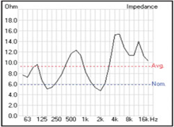
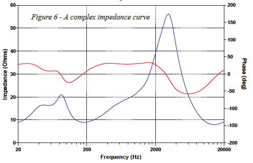
The Common Loudspeaker File Format includes the loudspeaker impedance curve at one-third octave resolution (Figure 6). The average and nominal values are displayed on the impedance graph. The average, nominal and minimum impedances are listed in text boxes.

This gives the loudspeaker designer a great deal of information for interfacing the loudspeaker with the amplifier. In addition to these ratings, a PDF info file can be attached to show the phase angle of the impedance (Figure 7).
As with household appliances, the main reason for knowing the load impedance is to avoid an overload condition. The amplifier is a constant voltage source.
While the power output increases with decreasing load impedance, the voltage output does not. It is prudent to avoid load impedances that cause the output voltage of the amplifier to sag more than 0.5 dB (5 percent) of the no load value.