Going The Distance
Another commonly raised objection to sub steering in general is that rearward rejection comes at the price of decreased output in front. This is true, with qualification. Decreased forward efficiency in sub arrays comes from two main factors.
First, certain array configurations result in delayed and/or out of polarity energy in the forward direction. The severity of this depends on the specifics of the array, which we’ll examine. The other factor is less intuitive: maximum summation from two subwoofers (+6 dB) happens only with a contribution of two equals: two sources meeting at a point in space at equal time, with equal level.
All of the two-element arrays examined here use physical displacement as part of the steering mechanism. In plain English, some of the boxes are placed closer to the audience than others, which creates a level offset and prevents us from ever achieving the full +6 dB. The good news is that level offsets are relative so as we get further from the array, the few feet of displacement matters less and less. (Mr. van Veen calls this “auto-efficiency.”)
Our measurement mics placed 20 feet out will see far more of a level offset than an audience member standing 60 or 70 feet back. To see how big of a deal this really is, we’ll be comparing the forward-going output of each array to the output of a standard side-by-side “broadside” sub array exhibiting the full +6 dB summation, which we’ll call the Gold Standard.
Inline Gradient Array, Non-Inverted
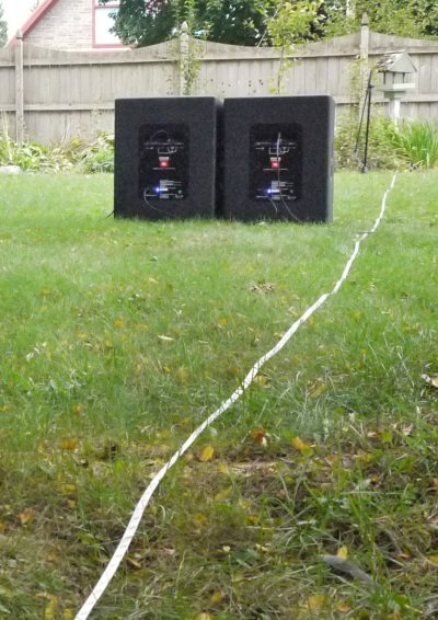
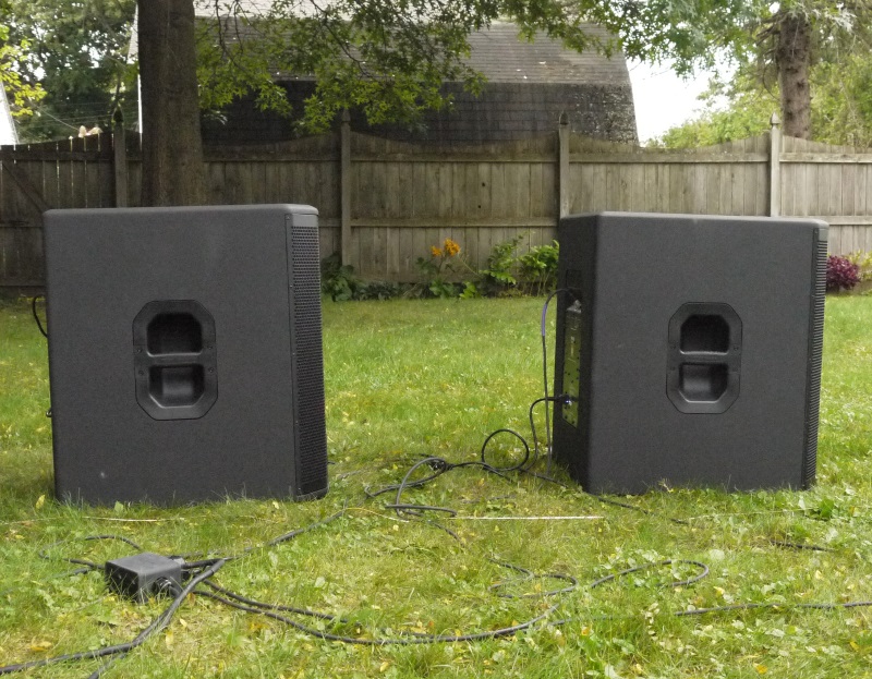
First up is an inline, non-inverted gradient array. (Sometimes this configuration is referred to as an endfire array, although I prefer to reserve that term for arrays consisting of three or more elements in a line. Hold that thought.) Figure 3 shows a side view of the physical configuration: one of the boxes placed closer to the audience.
This array creates a rear cancellation centered on a relatively small frequency range, and the physical spacing of this setup is determined by the frequency we want to cancel.
I usually aim for about 65 Hz, right in the middle of the sub range. The two elements should be placed with their acoustic centers spaced a quarter wavelength apart, which for 65 Hz is about 4 feet plus 4 inches (4’/4″). The front box, being closer to the audience, is delayed by the amount of time it takes the output from the rear box to catch up. We can easily calculate that sound waves travel 4’/4” in about 3.8 milliseconds (ms).
In practice, the timings can be slightly higher, since the sound from the rear box has to wrap around the front box, rather than passing straight through it “as the crow flies.” For this reason, performance will be better when delay values are determined with an analyzer rather than a tape measure.
Figure 4 shows the situation in front of the array: the magnitude panel on top shows that the front box (blue trace) is louder because it’s closer to the mic – this is the aforementioned level offset, which will shrink as we move away from the array.
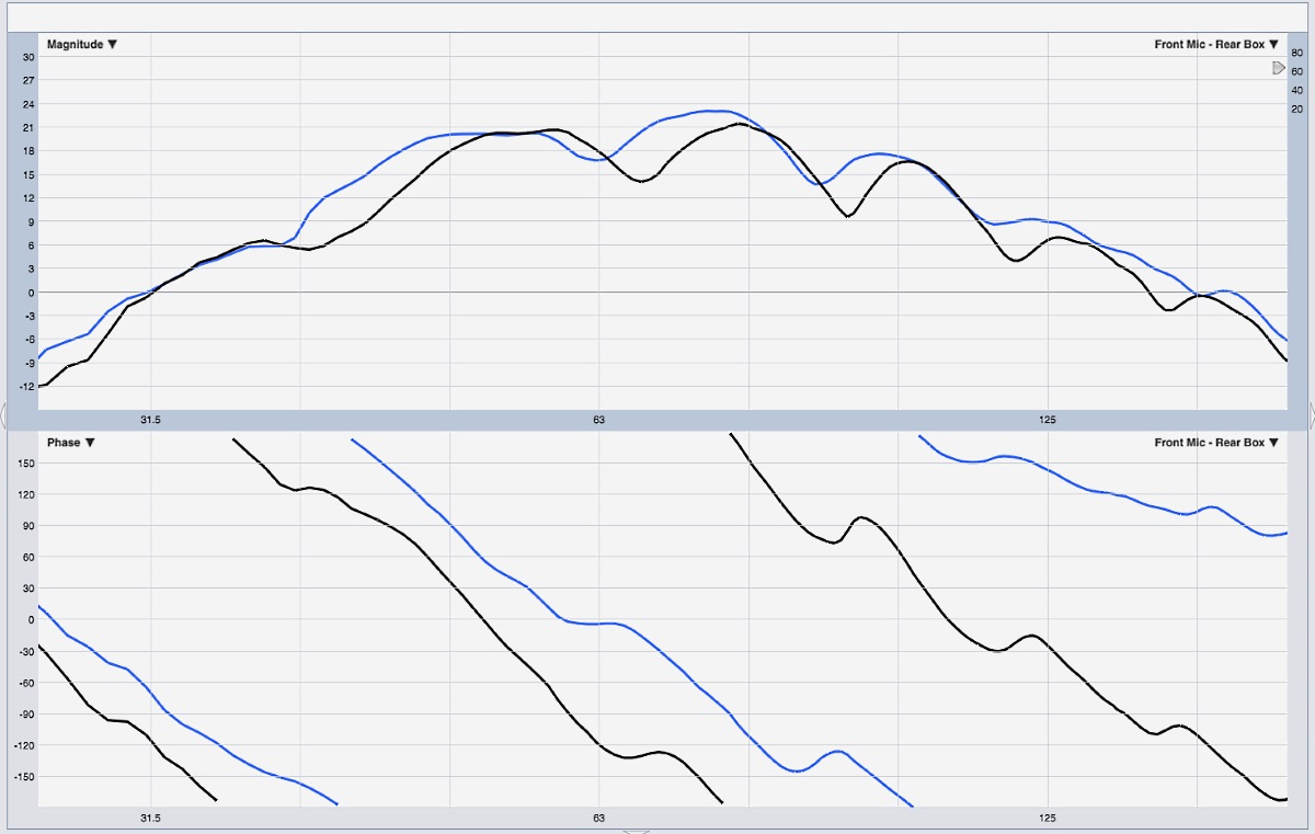
The bottom panel shows the phase response. This isn’t meant to be a dissertation on interpreting transfer function graphs, so those unfamiliar with decoding phase traces will be well served by this basic relationship: a steeper phase slope means more time offset. The black trace, representing the rear box, has a steeper slope because it’s farther from the mic and so its output takes longer to arrive.
To align this array, no calculations are necessary – just add delay to the front box until its phase trace tilts down to match that of the rear box, which tells us that we’ve got matched arrivals out in front.