1) Continuous Sine Waves – simple, unambiguous, and worst case with regard to current draw and power dissipation. Easy to generate, easy to measure. I mentioned my affinity for power ratings based on continuous sine waves in part 1.
2) Pink Noise – more “real-world.” The crest factor and bandwidth are more “music-like,” yet there is still enough stability to allow a “one number” rating to be estimated from an analog meter or bar graph.
3) Tone Burst – music contains transient events that can have very high amplitude and very short duration. I used Don Keele’s Peak Tone-burst test for this purpose. The spectral content and duty cycle can be sculpted to emulate a kick drum, staccato bass guitar, or whatever, but in a way that is completely repeatable and measurable.
I also used Don’s Tri-Tone Burst Generator, a program that runs under Igor, to produce the tone bursts. A center frequency of 80 Hz was selected to emulate the spectral content of a kick drum. The tone burst includes 6.5 cycles of three sine waves spaced at 1/3-octave and centered at this frequency.
The Amplifiers
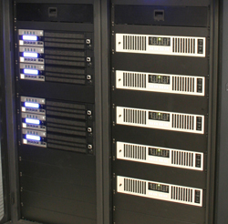
I selected three amplifiers to test. They all claim output power in excess of 1 kW, but there are significant differences between them in terms of ratings, features and price. The measured data is mainly useful for seeing how each performs under various signal types and load conditions. Here is a little background on each.
The first is a QSC PL380 that I use for loudspeaker power testing on a regular basis (typically in bridged-mono). It is analog by design. DSP processing and control is available, but I don’t have the required module, etc.
The second is a Crown I-Tech 9000 HD that I use in SynAudCon training classes. It has extensive on-board DSP and I monitored its performance with the company’s System Architect software.
The third is a Lab.gruppen PLM 20000Q that is on loan for evaluation. I used two of the four channels. While these models are apples, oranges and pears, they are all multikilowatt rated amplifiers and are at or near the top of the product line for each manufacturer.
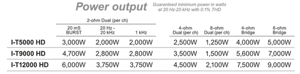
Amplifiers have many power ratings, based on load impedance, number of channels driven, signal type, etc. Most manufacturers provide a ratings matrix for a sine wave signal. See Figure 4 for an example.
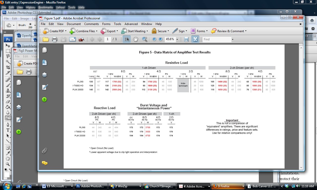
It gets even more complicated when you perform the testing for multiple signal types for both resistive and reactive loads. Since this is an article, not a book, I have only presented some of the results in the data matrix (Figure 5).
I monitored the current from the electrical circuit during the testing. The 30 amp breaker didn’t trip until about 40 amps. I should again emphasize that these amplifiers need a lot of utility power, along with special cabling and connectors to produce their rated sine wave wattages at 4 ohms.
I tested each amplifier’s open circuit output voltage as the first test. This basically means “disconnect the load and see what the amplifier’s output voltage is looking at air.” This is a useful reference for considering what happens under load.
An Open-Circuit Sine Wave Reference
None of the amplifiers had any problem maintaining their open circuit sine wave voltage into a 8-ohm load, even with two channels driven. All of them could produce their open-circuit voltage into 4 ohms, but fans were on “high.” Amplifier ventilation would be a definite issue for 4-ohm loads and low crest factor signals.