KEEP IT SHORT
The good news for most live sound applications is that we don’t have to tolerate extremely long wire runs. By locating power amplifiers near the loudspeakers we can keep wire runs reasonably short. At these shorter distances we can easily afford heavier gauge wire.
While power losses are now manageable, it is worthwhile investigating the next dominant consideration in sizing speaker wire. Frequency response errors will be caused by the voltage divider created between the wire’s fixed resistance and the loudspeakers changing impedance versus frequency.
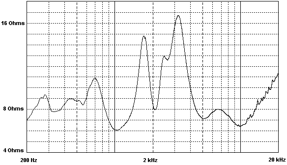
Figure 2 (above right) and Figure 3 (below right) shows two representative loudspeaker impedance plots, pulled from the Internet. These are not offered as either worst case or typical.
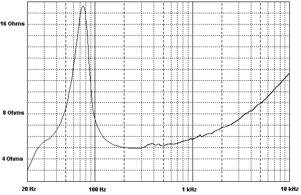
From the impedance plot in Figure 2, if we ignore the extreme low frequency, this loudspeaker exhibits a maximum impedance greater than 17 ohms, with a significant region of the upper bass down around 5 ohms. Meanwhile, Figure 3, while more complex, covers a similar impedance range, with a maximum around 16 ohms and a minimum around 6 ohms.
To derive a frequency response error we need to compare the drop at maximum impedance to the drop at minimum impedance.
The equations below calculate that drop for a given wire resistance. Note: to simplify this analysis we will assume all loudspeaker impedances to be resistive.
While not strictly accurate, loudspeaker impedances will typically be resistive at impedance minimums and any errors caused by load phase angle at the impedance maximums will not be significant for the sake of this analysis.
Minimum Voltage drop= V max = Z max /(Z max +Z wire)
Maximum Voltage drop= V min = Z min /(Z min + Z wire)
Frequency Response deviation= FR max = -20 Log10 (V min/ V max)
Solving for 1-, 0.5-, and 0.1-ohm wire resistance we get:
- Loudspeaker 1 ohm 0.5 ohm 0.1 ohm
Spkr 1 (17/5) -1.09 dB -.57 dB -.12 dB
Spkr 2 (16/6) -.81 dB -.42 dB -.09 dB
Another related consequence is how wire resistance degrades effective damping factor. While damping factor is usually though of as a power amplifier characteristic, in reality the wire selection can easily dominate actual damping available at the loudspeaker.
In the above examples, the 1-ohm wire would by itself cause a rather weak damping factor of 5 or 6 (regardless of the amplifier’s rated damping factor). Using the 0.1-ohm wire predicts a more respectable 50 to 60 damping factor, with some small additional degradation due to the amplifier’s output impedance.
Damping factor deserves a more extensive discussion, but for this exercise we will assume that the amplifier’s output impedance is small with respect to our wire’s resistance.
GAUGING GAUGE
It’s difficult to predict a precise threshold for audibility of frequency response errors. Controlled listening tests have suggested that differences as small as a few tenths of a dB can be audible.
To satisfy the dual goals of minimizing frequency response errors and not degrading damping factor for the example loudspeakers selected, I am comfortable with targeting a total wire resistance on the order of 0.1 ohm.
Wire’s resistance varies linearly with length. To keep the total resistance below our target limit of 0.1 ohm we must first project the length of our desired wire run, and then select a wire gauge whose resistance per unit length keeps us within the total resistance budget.
Don’t overlook that the wire length is actually twice the run distance as we must consider the feed to and return from the loudspeaker as effectively in series. We must also add in contact resistance for the connections at all ends.
Lets look at how this works out for a practical example of a 20-foot run. First, we double that to 40 feet to establish the true signal path length. Then we need to account for contact resistance. I’ve seen Neutrik Speakon (or copies of that connector) rated as low as 1mOhm (1/1000th ohm) per contact when new, and guaranteed < 2 mOhm over life. Because there are four connections in our total path lets budget .008 ohms for connections. Subtracting this 0.008 ohms from our 0.1-ohm target leaves us .092 ohms for wire. Dividing this 0.092 ohms by the 40-foot length calculates out to 0.0023 ohms per foot. Plugging this into the equation for wire gauge -
- AWG = 10 ×log 10 R +10 (note R is per 1000 feet)
We get: AWG = 10x log 10 (2.3) +10 = 13.6 gauge
This is a little cumbersome, but once you have established an appropriate gauge for a nominal run length with your specific system. This gauge can be scaled up or down for other run lengths.
Wire resistance changes linearly with length. It changes non-linearly with gauge. A convenient property of wire gauge is that the wire’s resistance will double for every 3-step increase in gauge (AWG). Conversely the resistance will drop in half for a 3-step decrease in gauge.
Based on this same example and rounding off to 14 AWG, we can expect similar performance from a 40-foot run using 11 AWG wire, and a 10-foot run would only need 17 AWG. This numbering convention gets a little unusual below “0” AWG.
One step below (larger than) “0” is “00”, and “000” is two steps larger than “0”. I don’t expect to see speaker wire this large, as they would be very difficult to effectively interface with amplifiers and loudspeakers.
Using this example to size wire for your system will get you in the ball park, but it will be more accurate to use actual impedance specifications for your loudspeakers. Manufacturers of professional loudspeakers routinely publish this information.
Remember, use only the impedance max/min deviation within the audio bandwidth of interest. It doesn’t matter what a tweeter’s DC resistance is or a woofer’s 20 kHz impedance, since you won’t be listening to them there.
You also may want to tighten or relax the acceptable frequency response deviation. Better yet, look at your loudspeaker’s typical frequency response and determine if the response errors caused by your wire losses are additive or corrective.
While I don’t suggest trying to dial in corrective equalization using wire losses, if the error is making your system flatter you can afford to be less aggressive in sizing your wire AWG as long as you keep damping and power losses under control.