My pandemic experience got off to an uncertain but thankfully healthy start. I was in San Diego starting the second leg of our spring tour (with Umphreys McGee) when the U.S. shut down. We all flew home and I began contemplating how to spend the foreseeable future.
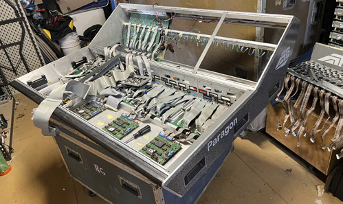
Not long after, some rare mixing consoles went up for sale in Nashville. I made a few phone calls and ended up purchasing an ATI Paragon II (P2) monitor console. I was busy re-purposing a Paragon P40D at the time, so work on this latest purchase amounted to a lot of speculation and even more diagrams. It simmered in planning throughout the lockdown and beyond.
Three years later, I decided its fate.
From The Top
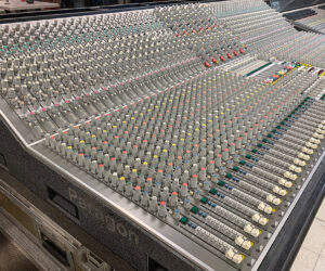
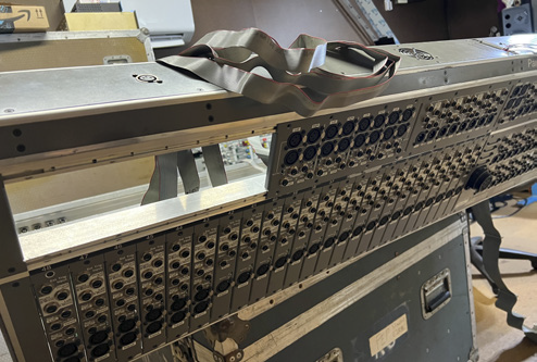
I drew up plans to convert the full-sized console into a sidecar with half the input channel strips. The more compact 52-inch width would be a much easier fit for modern venues than the original 96 inches. The original configuration for the P2 was 42 mono input strips and 6 stereo input strips, each with a very high quality mic preamp, sweepable high and low pass filters, 4-band fully parametric EQ (3-band on the stereo), compressor and gate. No other analog console I know of ever provided dynamics on every input channel.
The sidecar now contains 18 mono and 6 stereo input channels, combined with 8 stereo return channels, yielding a total of 46 inputs. The entire original output section remains: 8 stereo group/auxes, 18 mono group/auxes, 2 master mix buses and 8 VCAs.
I used the information gathered from that previous Paragon P40D project as a guide while planning my disassembly process. It still took hundreds of measurements and dozens of sketches to determine precisely where to cut.
My first decision was also my hardest. Do I remove the left side or the right? I decided to keep the right side due to the location of the incoming power connections and their distribution. If I had kept the left, all that cabling would have had to be redesigned and reconstructed. No need to add further risk to an already risky project.
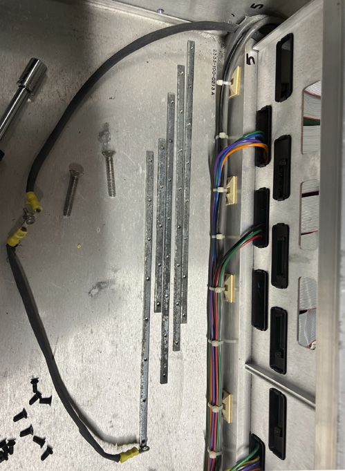
The Paragon consoles were built on custom aluminum extrusions cut with slots designed to contain steel strips with threaded holes for the channel strip screws. These steel strips are fully removable. A very flexible and modular design.
As I started taking everything apart, I set up stations to organize every component for easy reassembly and began rigorously documenting the internal cabling. I pulled all the channel strips, cover panels and end plates. Every screw and bolt went into a WD40 bath in the ultrasonic cleaner. After cleaning, I applied steel bluing solution to darken them and prevent rust.
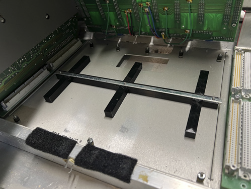
Now ready to move on to the frame, I removed the upper aluminum extrusions from the aluminum side plates first, working from the top down. Then I removed the left side plate from the two bottom frame extrusions. There were seven extrusions in total and I was able to disassemble five of them. The bottom two remaining extrusions were integral to the backplane used for interconnection between the fader strips, along with the automated muting PCBs.
I left that system assembled with the power wiring connected and carefully laid the wiring across the backplane. Then I wrapped everything in shipping wrap for protection from dust and debris.
Pivitol Point
Everything up to this point was reversible. Now I had arrived at the pivotal point: choosing where to cut the frame extrusions. I spent hours taking more measurements and making more sketches. Verifying that the existing wiring and cabling would fit and work as intended.
From my previous Paragon P40D project, I had learned that it’s better to be 0.5 mm to 1 mm over length to allow for some wiggle room between channels, but not so much as to expose an unsightly gap. But if it’s cut too tight, the last channel won’t fit. And this is no place for shims. I calculated. Then I decided where the cut should be and marked it.
Then I did the whole process again to make sure that was the mark. Then I did it again.

I wasn’t under any deadlines so I decided to wait until the next morning to make the cuts. It’s pretty easy to cut this extrusion. I’m guessing it’s a 7075 alloy, fairly easy to cut using a carbide tipped blade on a chop saw. The five loose extrusions were easy to cut, but the final two, forming the base and integral to the backplanes, had to be cut in place. That required significantly more prep work.
After the cutting was finished, the reassembly could begin. I started by carefully removing all of the aluminum shards that were trying to infiltrate my shrink wrapped backplanes. Plenty of compressed air and brushing. After I was certain all was clean, I removed the shipping wrap and inspected everything for dirt and debris.
I tapped new threads into the holes on the freshly cut ends of the extrusions, which simplified the matter of bolting the large parts of the frame back together, and reattaching the end plates. Then it was time to test fit the channel strips. To my immense relief, the last channel fit into place without forcing or leaving an unsightly gap. Whew.
Following the test fit, I took the channels back out and began the process of reinstalling the power distribution panel and verifying that all those connections were secure. Once the power and backplane were in place, I attached the power supply and powered up for the first voltage check. All of the voltages were correct and in the proper place on the terminal block. I felt confident that it was safe to reinstall the channel strips and continue testing.
During reassembly I had my first major setback. The backplane was originally attached to the bottom plate using rubber standoffs with threaded ends. Over time the unstable rubber in those standoffs shrank and got shorter. So when I tried to install the fader strips, the shortened standoffs allowed the backplane to deflect, which prevented the two 120-pin connectors from properly seating. The gap in the connection was 1-2 mm, enough to cause issues.
To solve this serious problem, I designed and 3D-printed some new standoffs in TPU flexible filament so they would have some damping effect, but still be stiff enough for a solid connection. The final fit was perfect, with a safety margin to account for frame flex in shipping.

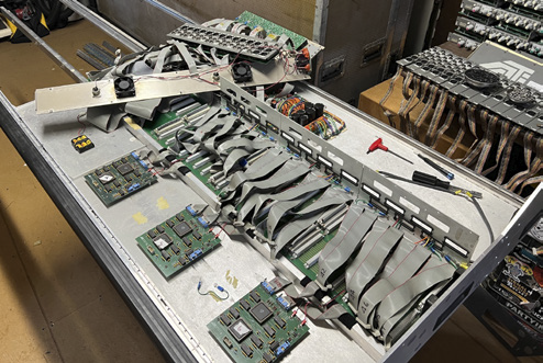
With that hurdle overcome, I continued populating the desk, giving special attention to all of the ground and power connections. That’s where most of the noise issues originate in large desks like this one. The audio and control signals are routed internally via ribbon cables. Lots of gray ribbon cables. The design engineers did a wonderful job with these interconnects, though, and they are well-routed and field serviceable.
A New Twist
Umphreys McGee tour dates and the holidays intervened, so the project was put on hold for a month or so. Then I was approached by a potential buyer and suddenly I was under a time crunch for an upcoming deadline.
And there was a twist. The new owner needed a matching road case. After weighing all the options I got to work measuring the original case, very well made by Spectrum Cases, for modification. After figuring out the structure of the corners and internal bracing, I started cutting with a variety of saws and drills. I kept one end plate whole and removed the minimum amount of rivets to free it. Off with the wheel board and then I could remove the excess length from the original panels. I had to drill new holes and reattach one pair of casters, touching up the paint to look factory. I even shortened up the dog house and relocated its latches.

Assembly of the case was straight forward from that point. A bunch of clamps and a rubber mallet realigned the rivet holes and after a lot of popping, the case was 42 inches shorter and just as tough as new.
That left two weeks for testing and any repairs that might be needed. The downside of testing a console like this is the vast number of options and routing paths available, so I made a chart to help with documenting the results.
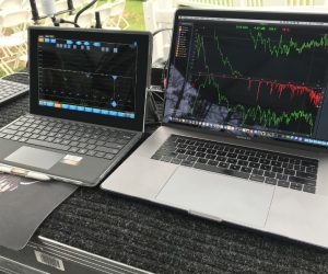
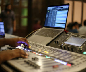
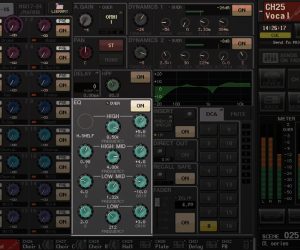
The easiest way I’ve found to do this is to use Smaart software, from Rational Acoustics, to generate a pink noise signal and inject it into each input channel. Check the mic preamp for proper operation, pan, high-pass and low-pass filters, 4 bands of EQ, compressor and gate.
Results are displayed on both the RTA and Magnitude graphs. I check for proper output on the direct outs and inserts as well as the source selections for those. Then I route that signal to all of the outputs and verify their level and frequency response. It worked out to 62 tests per input channel, times 24 channels, plus 8 aux returns, with 45 tests each.

There were also VCA and muting tests along with fans and ancillaries – in total, about 2,100 test points. I only found three issues: a bad 24-volt fan and 2 flaky VCAs. Easy fixes. I was very happy with that result.
The final product is a power house of an analog desk ready for new life on the road again.