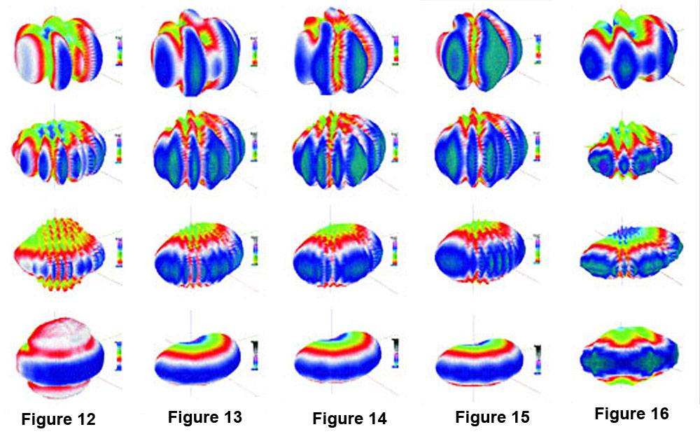
Figures 12 – 16 (below) show the 3-D directivity balloons for several “real world” array configurations for frequencies in the voice range.
The geometric origin is 1 meter for each array, a distance that is great enough to remove the physical conflicts between the devices.
Figure 12 shows an array of small sound columns that have the typical broad horizontal pattern and controlled vertical pattern. The lack of pattern control produces significant lobing at all but the highest frequency considered.
At this frequency, the lobing becomes so dense that the response actually becomes smoother. Dense interference is a common technique used by sound system designers. As the lobe density is reduced (lower frequencies) the coverage becomes more uneven.
Figure 13 shows the resultant radiation patterns when the column loudspeakers are replaced with medium-format horns having a 60-degree nominal horizontal coverage pattern in the 2 kHz octave band. The coverage is much more even than in the previous example.
As with the previous array, these devices are positioned on the surface of a sphere by using a common distance back to a “virtual” physical origin. This arraying technique produces physically appealing arrays, but unfortunately does not compensate for the fact that the acoustic centers are not reconciled.
As such, significant lobing is present in the radiation pattern at the lower octave centers where the radiated pattern is wider than the nominal coverage.
Figure 14 shows the same configuration, but with the center loudspeaker advanced physically by one foot. This makes the array non-spherical, which (ironically) produces an improvement in the evenness of coverage in the 500 Hz and 2 kHz balloons.
Figure 15 shows the same configuration, but with the center device delayed electronically in an attempt to “compensate” for the 1-foot advance. This demonstrates that the acoustic center of a device is a physical characteristic and cannot be moved electronically. While a delay can certainly alter the radiation pattern of the array, it is not a direct substitution for the repositioning of a device.
IMPROVING PERFORMANCE
Array performance can be improved by using devices whose directivity holds up to a lower frequency. This means a physically larger device.
Figure 16 shows the result of substituting large-format 60-degree horns for the medium format devices in the previous figures. The increased pattern control in the 1 kHz and 2 kHz balloons is apparent.
The bandwidths of these devices do not extend to 2 kHz, so the high frequency response was achieved with additional devices, coaxially mounted within the large-format horns.
Since using a larger format produces improved behavior, it is reasonable to expect that this improvement could be extended to lower frequencies if devices of sufficient physical size were used. Since the acoustic wavelength doubles when frequency is halved, the required size at 500 Hz would be twice that required at 1 kHz (8-foot mouth size!).
The wide horizontal coverage problem is one of the greatest challenges for the system designer. There currently exists no ideal solution, but there are certainly methods that work better than others.
Some conclusions of this and other studies are:
• Pattern control is essential if the goal of the array is to emulate a single device.
• Arrays of low-directivity devices should be avoided.
• Arrayability is frequency-dependent. What works at one frequency may not work at another.
• Spherical arrays are esthetically pleasing, but do not produce a common acoustic center.
• Misaligning devices (either physically or electronically) may yield a frequency-dependent improvement in response.
• Moving a loudspeaker produces a different result than delaying it.
• Different array techniques should be used at low frequencies than at high frequencies (i.e. vertical line arrays).
Because architects and their clients insist on building rooms that are too wide to be covered with a single loudspeaker, the wide horizontal coverage problem will be an ongoing one.
This article should alert the designer and buyer alike to the caveats of the horizontal array, and help them identify designs that provide an adequate level of performance for a given application.