Let’s return again to our light bulb example, and this time let’s run the AC at a frequency of 120 Hz. Since the light bulb filament is inductive, it would present a higher impedance to their higher frequency, and the bulb would be dimmer.
Through a pure inductor, doubling Ƒ also doubles XL and thus passes half the voltage. “Half the voltage” is -6 dB, which is why a simple single-pole crossover filter has a slope of 6 dB/octave. (Remember, an octave is doubling of frequency). To create steeper slopes, we cascade reactive elements. A 24 dB/octave filter circuit has four reactive elements that contribute 6 dB/octave each.
If impedance varies with frequency, why so do we have loudspeakers labeled “Impedance: 8 ohms”? The truth is that the Z rating on most loudspeakers is a worst-case scenario.
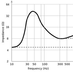
Many loudspeakers have impedance curves that look like roller coasters. We usually want to know the worst-case rating – the lowest point on the curve – because this tells us the most load that the loudspeaker could place on the amp.
Remember, lower Zs translate into higher loads on the amp since there’s less to oppose the flow of current. So an 8-ohm-rated loudspeaker probably exhibits a much higher impedance throughout most of its frequency range. The rated impedance is always higher than the lowest point on the curve. The IEC standard says that the rated impedance cannot be higher than the low point * 1.2. So, an 8 ohm loudspeaker could have a Zmin closer to 5 ohms.
Very low impedances are undesirable because the amp is approaching a short-circuit (0 ohms). In the sub-2-ohm range we have to deal with a whole slew of unpleasantries, including decreased amplifier lifespan, increased distortion, higher current draw, overheating, smoke, fire, and loss of employment.
Matchmaker, Make Me A Match
Early audio technology used an “impedance matching” approach. The source and the load had the same impedance, which resulted in a large power transfer between the devices. This was necessary at the time, since early devices needed the power. Unfortunately, there was a 6 dB voltage drop under optimal circumstances, and efficiency was poor.
Early telephone systems used this approach, standardized to 1 mW of power at 600 ohms. If you solve for voltage, you get .775, which is the origin of the .775 v = 0 dBu reference standard still in wide use today.
Modern systems use intentionally “mismatched” impedances. It was determined that if the load impedance was at least 10 times higher than the source’s, voltage transfer would be maximized, avoiding a lot of headaches. If the load impedance is high, the source doesn’t “see” a big load, and current demands are minimized for a given signal voltage. This reduces most of the signal chain to primarily voltage-only interactions.
Since cable losses are largely caused by current flow (power lost in cable = I2R, which R is the resistance of the cable and I is the current flowing through it), exchanging our signals as voltage only means negligible line loss, which is why a 200-foot snake is no problem. Cable losses are caused by voltage drop across the wire resistance, which results in less voltage across the load. Line loss is considered negligible if the wire resistance is less than 5 percent of the load resistance.