
It may not seem so at first blush, but there are few concepts as pervasive in live audio as the concept of impedance. It’s relevant to microphones, direct boxes (DIs), preamps, processors, amplifiers, loudspeakers, equalizers, crossover filters, and even the cables that connect them all together.
In this article we’ll explore the principles of impedance, and examine how these concepts apply directly to our work in the field.
Ohm Sweet Ohm
In order to understand impedance, we need to start by looking at the three fundamental electrical principles of voltage (E), current (I), and resistance (R). This would be an entire article on its own, so we’ll just have a quick review here. Traditionally, these concepts are introduced using the venerable, if limited, metaphor of water flowing through a pipe. But why talk about water when you can talk about cake? Here’s a more engaging analogy:
Imagine the fabric bags of frosting that bakers use to decorate cakes. Squeezing the bag forces the frosting out a nozzle in the bag’s corner. The flow of the frosting would be analogous to current (I) which is the flow of electrons in a circuit. The frosting flows because of the pressure applied to the bag, just as current flow is caused by the application of voltage (E), which is, more or less, “electrical pressure.” The nozzle resists the flow of frosting, just as resistance (R) opposes current flow in a circuit.
If we wish to increase the frosting flow (increase current), we can neither squeeze the bag harder (increase voltage) or use a nozzle with a larger opening (decrease resistance). These relationships are expressed in the formula E=IR, known as Ohm’s Law. Voltage is measured in volts, current in amperes or amps for short and resistance in ohms, which is represented by an Omega (Ω).
Add to the mix that you can multiply voltage times current to get power (P) in watts, and with a little algebra we can calculate all four circuit parameters – P, I, E and R – if we know any two (Figure 1). You probably don’t need to worry too much about committing all that to memory – if you use the formulas regularly, they’ll become second nature. It’s really the same idea stated a bunch of different ways. The important thing to realize is that a change in any of the variable affects all the others.

In North America, residential electricity runs at 120 volts. We can calculate that a 100-watt light bulb draws a current of .83 amp and has a resistance of 144 ohms. Now let’s swap out the 100-watt bulb for a 60-watt bulb. The power is less, but the voltage is still 120 volts, which means the 60-watt bulb has a higher resistance – the voltage is unable to push as much current. Ohm’s Law predicts a resistance of 240 ohms, and a current of .5 amp. For a given voltage, increasing resistance causes a decrease in current.
It’s Getting Hot In Here
But there’s a problem – if you use an ohmmeter on a 60-watt light bulb, you’ll get a value for less than the expected 240 ohms. We’re missing two critical puzzle pieces. The first is that incandescent bulbs get hot. Very hot. In fact, over 90 percent of their power is dissipated as heat, not light. What matters to us is that resistance increases with temperature. This is why the giant superconducting magnets in particle colliders are cooled with liquid helium – to keep the resistance as low as possible.
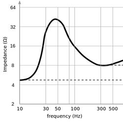
It’s also why the response of a sound system changes as it plays louder. Warm voice coils have higher resistance, and pass less current from the amplifier. This is part of the reason we have system limiters – a loudspeaker can only convert (“transduce”) so much power into sound. Past a point, it doesn’t get louder, it gets hotter. The heated coils in the loudspeakers lose efficiency and headroom, an effect called power compression. In the extreme, this heat buildup can be the kiss of death to a system – there’s a reason we refer to failed components as “burned out.”
It takes a pretty robust rig to remain linear all the way to its limits, fighting the changing resistance as the program materials heats the voice coils, but the last few years have seen more attention paid to this issue by manufacturers. For example, this is the issue that Meyer Sound is tackling with its LEO family of loudspeakers. So that’s one piece of the puzzle: a cold light bulb will show a lower resistance than a bulb heated to operating temperature.