By using high-rate crossover slopes, you’ll automatically minimize the portion of the spectrum that’s affected.
Unless other mitigating factors prevail, 48 dB-per-octave should be the starting point.
Even if there is poor summation at, let’s say, a 1 kHz crossover point, the loudspeaker will only be affected at a narrow bandwidth surrounding that center frequency.
Plus, there’s plenty that can be done to improve the summation because we don’t want to settle for even a small affected area, do we?
Especially when it falls at about 1 kHz, which is the upper region of the all-important vocal frequency range, and smack-dab in the middle of the first and second vocal harmonics.
Harmonics: Love ‘Em Or Leave ‘Em?
Without harmonics, all fundamental tones would sound much alike, distinguishable only by their pitch and their dynamic characteristics (attack and decay). Sound sources without harmonics would be like cooking pasta for a lifetime with only one flavor of sauce.
The fundamental frequency of a flute, a vocalist sustaining a note, and a string instrument would be hard to differentiate among. It’s the harmonic structure that causes a string to sound different from a woodwind, or a simple organ tone to differ from an all-out Hammond B-3 chord attack (Leslies spinning, of course).
The quality that we perceive in music and speech is the sum total of their fundamentals, their related harmonic structure, and their dynamic characteristics – and, of course, their pitch (or frequency). And so is our assessment of the quality of sound of a given loudspeaker.
So rather than getting incredibly fancy (leave this one to the mathematicians), we’ll simply look at the response of the loudspeaker on the analyzer. Remember to be careful about viewing on-axis and off-axis comparisons whenever trying different crossover points.
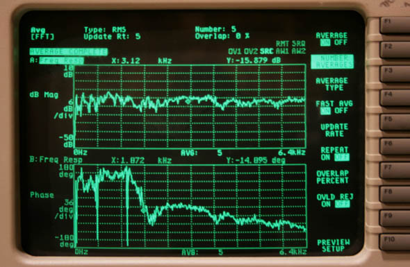
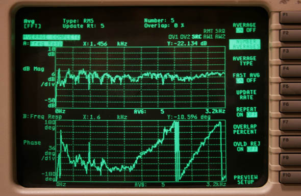
By adding small increments of delay to the driver that is furthest forward in the enclosure (usually the cone driver), the two sources can be aligned in the time domain to produce a flat frequency and phase response throughout the crossover region (Figures 3 and 4). A good target is to try to contain phase shift to no greater than ±30 degrees, though it’s entirely possible to reduce the phase shift to almost zero, which is better still.


If you’re not able to substantially reduce the phase shift at crossover by adding delay, then it’s time to break out the big guns. The inability to reduce phase shift to an acceptable level by the use of incremental delay indicates that the inherent roll-off of the LF or HF drivers (or both) is introducing a phase response alteration of it (or their) own. In cases like this, introducing an all-pass filter or a “phase” filter at the proper frequency and proper Q may be what’s needed.
To determine which driver needs help with its inherent phase shift, look at the frequency and phase response of each driver separately on the analyzer. Make sure that you‘re feeding them a broadband test signal (but not at a level that will cause damage), rather than a conditioned signal in which a crossover filter has already been introduced. You’ll quickly be able to determine what is causing the problem and then you’ll have an idea of how to attack it.
It’s no small feat to derive crossover settings that result in a perfectly flat phase response and frequency response crossover on-axis (plan on about a full day of trial and error), but it’s a whole other thing to make sure that your settings hold up off-axis. Be prepared to spend as much as two or three days to work through the process.
In the end you may have to compromise how flat the on-axis response is to improve the off-axis response. whether or not you decided to do so should depend on how the loudspeaker is intended to be deployed. If 70 percent of the listeners are positioned off-axis, then the answer is a no-brainer.
