New Driver Tech
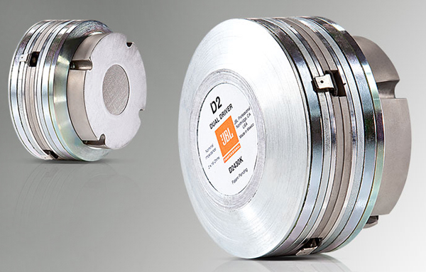
The “dual” aspect of the transducer approach has now been taken to a higher level in VTX V25 with the completely new D2 dual diaphragm dual driver, which, as the name suggests, merges two compression drivers into a single, compact transducer.
Two light weight, polymer-material, annular diaphragms with a V-shaped profile and dedicated phase plugs are employed in the D2 transducer.
The two annular diaphragms have the same effective radiating surface area as a traditional dome diaphragm, thereby providing equivalent SPL output.
There are three main benefits to the D2 approach:
1) Two separate voice coils provide twice the power handling capacity combined with reduced power compression due to improved heat dissipation;
2) The lower moving mass of two annular diaphragms has improved high frequency extension in comparison with the heavier dome diaphragm assembly; and
3) Dome breakup modes that result in frequency response irregularities and increased non-linear distortion at high frequencies are virtually non-existent for the D2 driver due to the use of annular diaphragms, combined with the polymer diaphragm material itself.
Specifically, the use of two annular diaphragms eliminates “choppy,” irregular frequency response above 10 kHz, accompanied by significantly decreased levels of nonlinear distortion. Essentially, since there is no dome there are no dome breakup modes.
Each diaphragm is loaded by its own phasing plug that has radial acoustical channels, and both phasing plugs are acoustically connected to a single acoustical load (waveguide) from a single aperture.
The effective radiating surface area of the two low-mass diaphragms is approximately equal to the effective area of a traditional dome diaphragm having the same voice coil diameter so there is no loss in overall output.
Because the overall volumetric displacement of two diaphragms is approximately equal to that of a single-dome diaphragm, this new transducer can be thought of as a compression driver with a single, lightweight diaphragm driven by two voice coils instead of one.
The low moving mass of each diaphragm assembly provides higher frequency mass roll-off, and the high internal damping of the polymer diaphragm significantly decreases non-linear distortion associated with high-frequency dome breakup modes.
What’s Inside
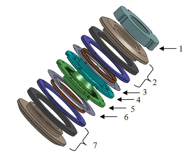
The concept of the dual driver can be scaled to different formats, and D2 units with voice coils of 1.5, 1.75, 2, and 3 inches in diameter have been developed and prototyped. Figure 1 presents an “exploded view” of the D2430K component assembly(three D2430K dual drivers are loaded in the VTX V25 enclosure).
As seen in Figure 1, two diaphragms (3 and 6) are vibrating in “push-push” mode, and are loaded by their corresponding phasing plugs (4 and 5).
The sound pressure signal is summed on the adjacent openings of their respective phase plugs and directed via radial channels to the central opening and then towards the exit of the driver.
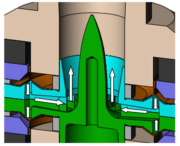
Figure 2 illustrates the central part of the driver and the arrows show the path of the acoustical signal.
The sound pressure signal is directed from the compression chambers through the slots in the phasing plug, to the radial channels, then to the central opening with the bullet, and then finally through the central bore to the exit of the driver.
Figure 3 shows both sides of the upper phasing plug. The rear phasing plug has a mirror image of the slots and radial channels.
The only difference is the central bullet. The orientation of the slots in the phasing plug is neither radial nor circular, as is typical for conventional dome compression drivers.
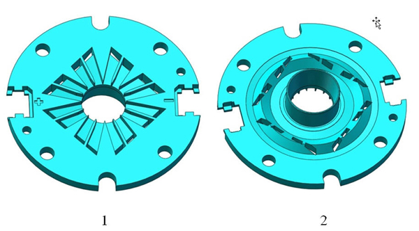
Instead, the slots are positioned diagonally with respect to the circular pattern of the phasing plug’s profile, i.e., they’re going “across” the compression chamber at certain angle.
This approach provides averaging of the acoustical signal “picked up” at different points across and around the compression chamber.
The diagonal position mitigates influence of both radial and circumferential air resonances in the compression chamber whose behavior at high frequencies is highly complex due to the partial vibration of the diaphragm.

