SWITCH OR DIGITAL?
Class-D designs are sometimes called “digital amplifiers.”
Note that the “D” in Class-D does not stand for “digital,” and this is a common misconception. (D was just the next letter in the alphabet when class designations were handed out!)
Class-D amplifiers operate the output devices as switches. The state of a switch can be thought of as a binary value (1 or 0), as in digital circuits like computers.
Some Class-D amplifiers take in digital inputs. In that case, they’re often referred to as “true digital” amplifiers, adding to the confusion.
Other classes of amplifiers, by the way, do not share this possibility. The bottom line here is that Class-D amplifiers are switching amplifiers, and they have much in common with switching power supplies.
Switches theoretically dissipate no heat. When a switch is closed (the “on” state), there is no voltage across it, and when it is open (the ”off” state), there is no current through it. Because power is the product of voltage and current, there is no dissipation in the switch, thus a theoretical 100 percent efficiency for Class-D.
However, transistors are far from ideal switches, especially at the typical 200 kHz to 2 MHz switching frequency. The transistors used in almost every Class-D amplifier today are MOSFETs due to their fast transition speed and low “on” resistance. Despite these limitations, Class-D amplifiers are typically 90 percent efficient in practice.
It’s important to note that a certain amount of power is lost during every switching transition. This is due to the imperfections of MOSFETs used as switches, such as finite switching times, dissipation of fly back current from the output filter through on state resistance, reverse recovery charge, and other practical circuit limitations. In essence, the higher the switching frequency, the lower the efficiency.
Class-D amplifiers have historically found homes in subwoofer applications due to conveniently low required bandwidth (allowing lower switching frequencies) and lower expectations regarding noise and distortion performance as opposed to raw power output.
Using Class-D in this application shrinks the power supply considerably and doesn’t stress the amplifier’s performance potential. Using Class-D in a full range application is more demanding.
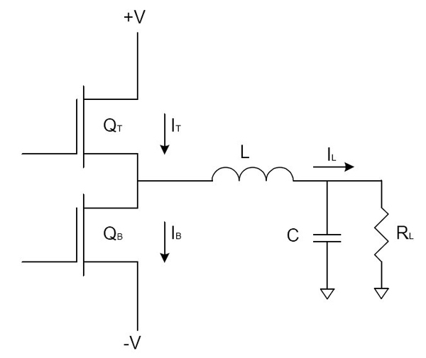
There are many variations of Class-D, so we will discuss the simplest form of Class-D, the fixed frequency PWM half-bridge, as an example. The output devices are switched with varying duty cycle, and the duty cycle of the transitions determines the average output voltage. An LC filter (called the output filter) is used to remove the carrier, and you are left with the desired output voltage, plus switching ripple. Figure 2 depicts this type of amplifier output stage.
Also in Figure 2, the transistors (MOSFETs) are turned on and off in a manner that prevents them from both being on at the same time (a condition known as “shoot thru”). The LC filter smooths these transitions to the load.

