OTHER ADVANTAGES
Class-D amplifiers handle reactive loads differently than linear amplifiers.
Operating the transistors as switches minimizes the voltage across them when reactive currents are present, keeping dissipation low.
Switching amplifiers have a few other advantages over linear amplifiers such as the elimination of zero crossing distortion and excellent transient response.
We haven’t discussed the transient response of the other amplifier classes, but will contrast Class-D with respect to the other classes regarding this important sonic quality.
In a Class-D amplifier, the power supply is not loaded heavily until the output is close to its limits; therefore, it has more power “on reserve” to tackle the sudden demand for current to the load.
Sonically, Class-D performs very well when compared to Class-AB or Class-A amplifiers of the same price range, while providing much higher efficiency.
What, then, is the downside to Class-D? Why aren’t all amplifiers Class-D? Theoretically, it is the perfect amplifier, dissipating no heat, and performing its amplification function as desired.
However, the audio performance of a Class-D amplifier has much to do with its practical implementation. The physical limitations of MOSFETs and the circuits that drive them make it difficult, but not impossible, to match the performance of Class-AB or Class-A.
The specifications where these limitations come into play are noise and distortion. It’s a difficult engineering task to produce a low-distortion low-noise high-power Class-D audio amplifier at reasonable cost. In fact, even in cost-no-object designs, achieving high performance is certainly challenging.
Timing accuracy is important to Class-D amps because the relative timing of the transitions directly determines the average output voltage. This means that any error in timing produces an associated error at the output.
If the errors appear as “jitter”, it creates noise at the output. If the timing error is dependent on the input signal, it appears as non-linearity at the output. Achieving perfect timing is not possible, but the closer you get to perfect timing, the closer you get to perfect output.
In theory, a Class-D output stage drives the output filter with a perfect square wave. In practice, the average output current affects not only the timing of the pre-filtered output, but also the “squareness.”
For instance, rise and fall times vary with average current, and so do some of the undesirable effects of component limitations, such as overshoot or undershoot. These problems are usually corrected with feedback such that the average output voltage is accurate despite the instantaneous inaccuracies associated with generating a high power square wave.
One important factor in Class-D performance is the “modulation technique” that is used to control the output stage. Modulation is the act of converting the analog (or digital) input to a pulse train. Modulation technology is a growing field, and complexity varies greatly from technique to technique.
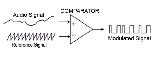
Class-D amplifiers drive their output devices with a modulated signal, essentially a conversion of the analog audio (variable voltage) to digital (again, “1” or “0”). As mentioned, there are a variety of ways to perform modulation, but for sake of simplicity, the “comparator method” will be explained.

Referring to Figure 3, the slowly moving analog signal is compared to a faster moving “carrier” signal, typically between 200 kHz and 1 MHz. If the audio signal is a greater voltage than the carrier signal, the comparator outputs a “1.” If the audio signal is a lower voltage than the carrier signal, the comparator outputs a “0.”
The output of the comparator can then be averaged, or filtered, to “demodulate” this digital signal back to analog. This filtering is performed by the amplifier’s output filter (after the output stage). The performance of the modulation process, as measured in terms of noise and distortion, depends greatly on actual circuit implementation.
OPEN LOOP
Feedback is used in most modern amplifiers to correct for power supply variations and output device non-linearity. An amplifier that incorporates feedback is called “closed loop”. An amplifier that doesn’t use feedback is called “open loop.”
The use of feedback is a broad topic with many intricacies. However, it’s notable to mention that almost every amplifier class relies heavily on feedback to make them perform well. Some amplifiers operate open loop with good performance, but this is a difficult result to achieve.
In the case of Class-D, feedback is especially difficult to implement when the output filter (and its associated phase response) is part of the “loop”, and in many Class-D amplifiers, the feedback is taken from before the output filter.
New topologies are being invented all the time. Combinations of Class-D with linear supplies or switching supplies, Class-AB amplifiers driven from Class-D amplifiers (used as supplies), multiple moving rails, Class-AB driving the power supply rails to control the load from the power supply center tap, and many other novel techniques exist. Covering them all, even briefly, is a challenge.
Tommy O’Brien is a power amplifier designer.
