And Now The Ugly World In Which We Live
Contrast this to a typical public address system squawking bad sound to the congregation. That which was good is replaced with misery.
You reach for a bottle of aspirin to calm the headache induced by a pair of blaring powered loudspeakers. Some of the problems encountered by audio designers/consultants include:
Excessive Reverberation, such that articulation and clarity is poor.
Echo, where a discrete sound reflection returns to a listener more then 50 milliseconds from the direct sound and is significantly louder then the reverberation sound.
Flutter Echo, repeated echoes that are experienced in rapid succession that occur between two hard parallel surfaces. All echoes ruin the acoustic properties of a room and a flutter echo is particularly damaging.
Coloration Due To Reflections, where a reflection destructively recombines with the direct sound, modifying the frequency response in the process. These are non-minimum-phase colorations as correction with equalization is not possible.
Delayed Sound, from coupled volumes (contamination from adjacent rooms storing sound energy and then returning the energy to the main room).
Psychological Reconditioning, a common problem for the clergy and congregation to be so preconditioned by bad sound that they become resistant to change and find it difficult to (at first) recognize good sound.
This can also work in the audio consultants favor when the customers are preconditioned by good sound and are willing to invest the required resources toward good audio design.
For those of us designing audio for houses of worship with a rectangular room, flat walls and probably a vaulted ceiling, some form of sound reinforcement is required. Through attention to detail and careful design of the audio system, the experience of the congregation can be non-aspirin inducing and the system simple to use.
Common Signal Processing Blocks
Let’s begin by looking at the universal signal processing chain common to all audio systems.
In the simplest systems these functions are accomplished in an audio mixer that feeds a pair of powered loudspeakers.
More sophisticated systems include equalization, compression, limiting, automation, feedback suppression, electronic crossovers and other tools of the trade. These days it is possible to include all of these functions in a DSP (digital signal processor).
One example of the signal chain from the minister’s microphone to the power amplifiers is shown in Figure 1.
The signal processing flow starts at the analog input. A 2-band parametric equalizer filters out-of-band low frequencies. The microphone signals are summed together in an automatic mixer. An AGC (automatic gain control) reduces the dynamic range and a high-pass filter in the side chain improves the performance of the AGC.
The level control can be tied to a pot on the wall or a smart remote. There is a feedback suppressor for good measure. A 2-way crossover supports a biamplified system. The 10-band parametric equalizers are utilized for both wide- and narrow-band corrections.
Generally, wide-band filters correct minimum-phase frequency response irregularities in the speaker drivers and in the room response.
Narrow-band filters are useful to partially correct non-minimum-phase related problems such as energy stored in room modes (reverberant energy).
A limiter could also have been added to protect the system from clipping if that feature is not included in the power amplifier.
Now let’s take a look at some of these signal processing blocks in greater detail.
Analog Input / Microphone Preamp
It’s surprising how often even experienced audio consultants will configure an audio input incorrectly. It’s important that as much gain as possible is accomplished at the front end of the system in the analog gain stage.
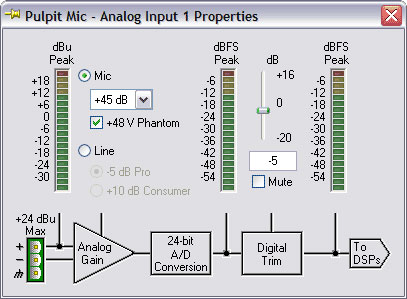
Any additional gain from digital trim after the input stage degrades optimum signal-to-noise performance. As an example, let’s set the input gain to a value of +40 dB.
One way is where the analog gain is set to a value of +45 dB and the digital trim is set to -5 dB (as in Figure 2), the measured input referred noise is -127 dBu.
A common (but incorrect) way would have the analog gain set to a value of +30 dB and the digital trim set to +10 dB (the author has seen this repeatedly), to give the same Mic gain of 40 dB—but now the input-referred noise is degraded to -114 dBu.
That is an increase of 13 dB for the noise floor, or a change (in the bad direction) of 8 dB in the maximum SNR (signal-to-noise ratio). Your exercise is to determine why the SNR was only degraded by 8 dB rather then the intuitively obvious value of 13 dB.
Answer: The noise floor does drop by 13 dB, but this combination of settings causes the analog input stage to clip at an input level that is 5 dB lower. Hence, the change in system SNR is 8 dB.
Applying attenuation after the input stage (rather then gain) reduces overload performance and so should be used with skill and discretion.
It is the proper technique to maximize noise performance.
Input Low-Cut Filter
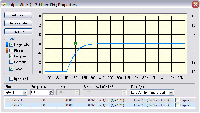
A very good idea is to add a low-cut filter set to ~80 Hz after the input stage to minimize the effects of undesirable low-frequency noises such as bumps and thumps that come from handling the mic and also wind blasts and pops from speaking too closely into the microphone.
In Figure 3, both 2nd-order filters are set to the same frequency to produce a 4th-order filter.
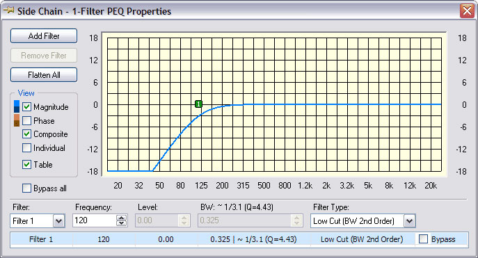
There should also be a low-cut filter in line with the SC (side chain) input of the AGC (automatic gain control).
This filter can be set to a higher corner frequency (such as 120 Hz in Figure 4) to improve the performance of the AGC by rejecting the effects of low-frequency noises.
The Auto Mixer
A Little Automation Buddy
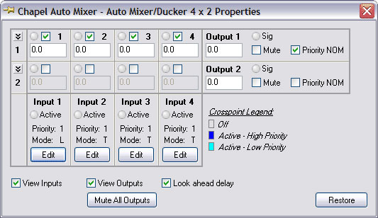
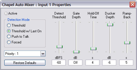
An auto mixer (shown in Figure 5) is a good idea when there is more then a single open microphone.
Auto Mixers combine the signals from multiple microphones and automatically correct for the changing gain requirements as the NOM (Number of Open Microphones) changes.
Threshold with “last on” is a useful setting for all microphones used in a worship service (Figure 6).
Unused microphones (input levels are below threshold) are gated. When the input of a microphone is above threshold then other inputs with a lower assigned priority level are ducked.
Automatic Gain Control
A compressor is the correct processing block in this link of the audio chain. Something is needed here to prevent exuberant preaching from melting down the congregation.
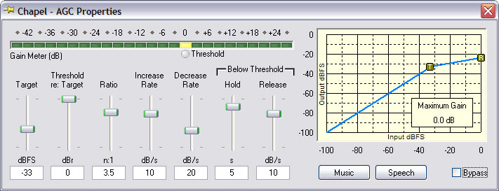
Surprisingly, an AGC can be very useful in this position but configured to behave more like a specialized compressor by using the settings shown in Figure 7.
The value of “Threshold re: Target” is set to have an offset of 0 dBr so that “Threshold” has the same value as the “Target.” “Maximum Gain” becomes 0 dB and the gain curve starts to look like a compressor but there are additional controls in an AGC for Hold and Release that are useful when the input level is below threshold.
These settings avoid the problems of compressor “pumping” when that exuberant loudspeaker is at the microphone as attenuation levels are held between spoken phrases. Then, when transitioning to a more reserved loudspeaker, the hold time (below threshold) is short enough to expire so that the gain returns to a normal level.


