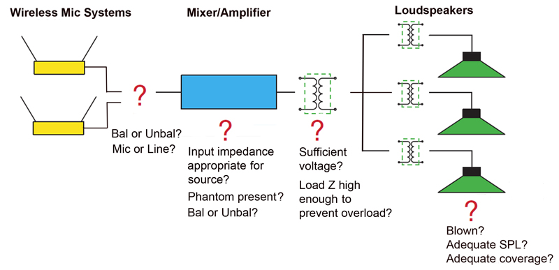
A test of the loudspeaker line with the ZM-104 impedance meter revealed that all loud-speakers were operating and that the total impedance was about 2,500 ohms.
The 1 kHz square wave was clearly audible from all of them.
Since voice coil impedance is typically about 8 ohms nominal, and three in parallel would be lower yet, there had to be step-down transformers on the loud-speakers.
These make the loudspeaker’s voice coil impedance appear as a much higher impedance to the amplifier.
This immediately suggests the need for a high voltage amplifier output.
The new amplifier is rated at 100 watts into 8 ohms, which tells me that its output voltage should be around 30 volts rms for a sine wave (and about one-third of this voltage for program).
This is possibly too low to drive a high-voltage distribution system. On the other hand, this place doesn’t need a lot of level so it might just be adequate.
Rather than order in a step-up trans-former (or root around for one in the “bone yard”) I decided to just try it and see how well it worked.
I maxed-out the wall mount attenuator in the chapel and slowly increased the output level control on the amplifier while talking through one of the wireless mics.
I was delighted to find that I could get adequate level out of the system with the available voltage, even though I had to turn it nearly all of the way up.

The installer had tapped the loudspeakers too high. The correct tap setting would be the one that produced the needed SPL at a higher amplifier output voltage (about 30 volts rms program for a 70.7-volt system).
Speaking loudly caused occasional flashing of the limit light which actually turned out to be a good thing. Since the amplifier limits rather than clips, the limit circuit could be used to prevent excess sound level if someone eats the mic – an all-to-common occurrence when you have people singing into lapel mics.
So in this case it ended up that driving a high impedance loudspeaker system from an amplifier without a high voltage output was better than stepping up to a higher voltage. You never know until you try, and trying is usually free.
This is not a recommended practice for a new design, especially one that might be expanded later. I always try to get a pretty high voltage (20-30 volts rms) on 70.7-volt lines and then tap it back at the loudspeaker to whatever is needed.
In this case, re-tapping the loudspeakers would be an ordeal, and there was no need to add any others to the system. I elected to break the rules and drive the loudspeaker system without a step-up transformer.
I drove the balanced input of the hear-ing assist system from the unbalanced auxiliary mixer output using the forward-
referenced wiring scheme. In the old system it was driven from the high voltage amplifier output, but its input was not configured to handle the high voltage.
The severe distortion had kept them from ever using the system. It now works fine and is in regular use.
Wireless Mic Reception
I walked the chapel with both wireless mics to check their reception.
