Q. What’s the difference between mic level, line level, and speaker (loudspeaker) level?
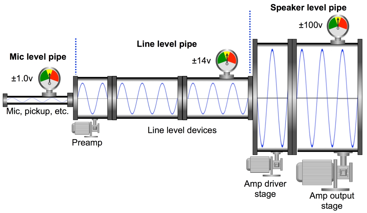
On one hand, this is a classic Goldilocks story: Papa Bear, Mama Bear and Baby Bear, but there’s more to it than that. Any of these three levels could carry a 1-volt signal, so let’s spell out the differences (Figure 3).
We’ll begin in the middle with line level, which is the standard analog transmission level between active devices (e.g., playback and a console input, console output and signal processor input). It’s also the level at which that signal is moved around inside a given device (e.g., within the internal stages of an analog console).
In the modern world, line level transmission goes between active devices, i.e. ones with DC power supplies. The nominal range is considered 1 volt but the key factors are the upper voltage limits and the output impedance.

Standard line level devices can handle up to 10 to 12 volts rms (+20 to 24 dBV) with an output impedance of <250 ohms (around 1/4-watt of power max). Such devices can drive multiple line level inputs without any worries but don’t expect it to drive an 8-ohm loudspeaker. Mic level is a state of necessity, one that we try to work our way out of as quickly as possible. It’s the product of passive devices that generate microscopic amounts of voltage and current, such as microphone diaphragms and guitar pickups. The voltages are so low (and/or output impedances so high) that they’re extremely susceptible to noise and will degrade further if we try splitting them to multiple inputs.
Therefore we use preamplifiers to raise them to line level as quickly as possible. There are some active devices that can operate at mic level (such as wireless transmitters) but this is usually more about matching their level with passive mics, and these devices usually have the option of line level output drive (use it!). And finally, there’s speaker level, with voltage ranging from tiny to dangerous and an output impedance of <0.25 ohm.
Speaker level is differentiated from the others by current (not voltage), which gives us the capability to drive 4-ohm loudspeaker loads without worry. Power amplifiers have three stages: Line level input section, drive section and output. The drive section elevates the voltage above line level and the output section supplies the massive current needed to generate real power to the loudspeakers. Amplifiers with higher power capability will utilize higher voltage levels in the drive stage and/or greater current capability in the output stage.
Q. What is harmonic distortion?
When we input a pure tone (a sine wave) into a sound system, we expect it to reproduce that signal and not to add extra tones. Guess what: they all do. The question is how much and what type.
Harmonic distortion is the addition of multiples of the input frequency (the fundamental). For example, a 1 kHz fundamental will yield harmonics of 2 kHz, 3 kHz, 4 kHz, etc. If we sum up the level values of the harmonic series, we can compare that to the fundamental level and determine the percentage of harmonics being added (the total harmonic distortion or THD).
So if the fundamental was 10 volts and harmonics added up to 1 volt, we would have 10 percent THD, which means that 10 percent of the output signal is different from what was put in. For a guitar amp this is all fine and good, but for a sound reinforcement system, not so much.
Q. What causes harmonic distortion?
There are a million possible causes for harmonic distortion and they vary widely by transmission medium, but let’s look at some of the big ones. We’ll start with the analog electronic and then add some other mediums.
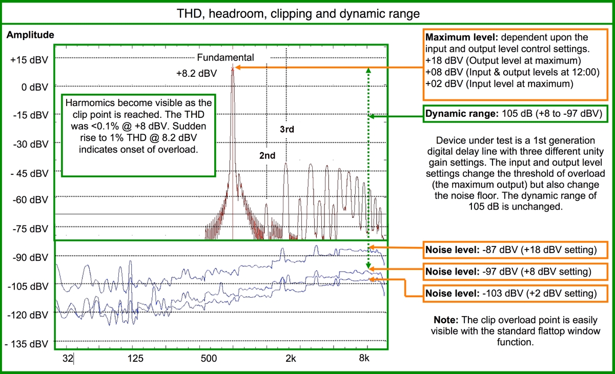
The easiest to grasp (and see) is clipping, i.e., sawing off the waveform top. The most common cause of clipping is reaching the limits of the DC power supply for that particular transmission stage. The DC supply voltage is like the outer edges of a pipeline. If the waveform is too big to fit in the pipe then the oversized parts are simply clipped off. The pipe casing for solid state analog electronic devices is extremely stiff. There’s very low distortion in this medium until you reach the limit and then it quickly rises to extreme levels (Figure 4).

Other mediums and devices have more gradual onsets, so let’s consider these. Magnetic devices such as transformers (or an ancient recording medium called magnetic tape) don’t have an exact point of clipping. Instead, they gradually “saturate” before giving in to hard clipping. As the signal approaches the magnetic energy storage limits of the transformer it begins rounding the waveform, more akin to a compressor. The rounding generates harmonics, but a far less complex (and more “musical”) series than hard clipping.
Mechanical devices such as loudspeaker and microphone diaphragms have a gradual onset that relates to the elasticity limits of the surrounds that hold the diaphragm in place. Think of this like stretching a large rubber band between your hands. Initially, it’s easy to stretch the band, but then gradually it requires more effort to further expand it before reaching its full limit.
Sending more level to a loudspeaker asks it to stretch the diaphragm further. The waveform is rounded and harmonic production commences when the diaphragm’s motions are retarded by the increased physical resistance. The medium of air itself has mechanical elasticity which you can easily simulate by pushing and pulling a balloon. Rising SPL causes increased distortion in the medium of air itself. The compression and rarefaction become more resistant as SPL rises and the waveform rounding increases.
