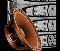
With a cone driver, the mass of the moving parts, and the stiffness of the suspension (surround and spider), are the key elements that affect the resonant frequency.
As a general rule of thumb, a lower Fs indicates a woofer that would be better for low-frequency reproduction than a woofer with a higher Fs. This is not always the case though, because other parameters affect the ultimate performance as well.
Re: DC resistance of the driver measured with an ohm meter, and often referred to as the “DCR.” This measurement will almost always be less than the driver’s nominal impedance.
Some users sometimes get concerned the Re is less than the published impedance and fear that amplifiers will be overloaded. Due to the fact that the inductance of a speaker rises with a rise in frequency, it is unlikely that the amplifier will often see the DC resistance as its load.
Le: Voice coil inductance measured in millihenries (mH). The industry standard is to measure inductance at 1 kHz. As frequencies get higher, there will be a rise in impedance above Re, because the voice coil is acting as an inductor.
Consequently, the impedance of a cone driver is not a fixed resistance, but can be represented as a curve that changes as the input frequency changes. Maximum impedance (Zmax) occurs at Fs.
Q Parameters: Qms, Qes, and Qts are measurements related to the control of a transducer’s suspension when it reaches the resonant frequency (Fs). The suspension must prevent any lateral motion that might allow the voice coil and pole to touch (this would destroy the driver). The suspension must also act like a shock absorber.
Qms is a measurement of the control coming from the driver’s mechanical suspension system (the surround and spider). View these components like springs.
Qes is a measurement of the control coming from the driver’s electrical suspension system (the voice coil and magnet). Opposing forces from the mechanical and electrical suspensions act to absorb shock.
Qts is called the “Total Q” of the driver and is derived from an equation where Qes is multiplied by Qms and the result is divided by the sum of the same.
As a general guideline, Qts of 0.4 or below indicates a transducer well suited to a vented enclosure. Qts between 0.4 and 0.7 indicates suitability for a sealed enclosure, and Qts of 0.7 or above indicates suitability for free-air or infinite baffle applications.
