As with airborne noise, structure-borne noise is conceptually easy to control.
Simply isolate the source from the structure. Isolation requires that the vibration energy be dissipated in some sort of elastic medium or that the path the vibration takes from the source to the structure be as inefficient and lossy as possible.
In practice this can prove to be very difficult. Many of the mistakes that we see in the field are not conceptual mistakes. Rather, they are mistakes in execution.
A small Evangelical church in Florida builds a new church. The designer, wishing to save money on HVAC ducting, located the mechanical room directly behind the rear wall of the sanctuary.
They took pains to seal the duct penetrations and of course they mounted the HVAC unit on isolators. Why then was the HVAC clearly heard in the sanctuary? It could be argued that the location of the HVAC unit so close to the sanctuary was a bad design decision.
The primary reason for the HVAC noise leaking into the sanctuary was because the contractor used the wrong isolators. The isolators were far too soft for the weight of the unit and were bottomed out, resulting in no isolation as they were unable to dissipate any of the energy at all.
The same thing can happen if the springs or rubber pads are too stiff. If there is no movement or compression of the isolators there will be no isolation. Most problems seen in the field are much more complex.
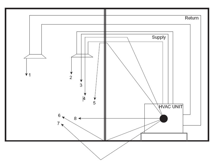
Figure 1 (below) illustrates some of the more common ways that vibration and noise can get from one space to another. It represents a common situation with an HVAC system located adjacent to a room intended for some use where the noise from the HVAC unit would be a problem. Each of the numbered arrows represents a path that sound can and does take to get from one room to another.
Please note that all the arrows emanating from one duct also apply to the other duct. They are not shown for clarity.
● Arrow 1 represents the vibration that travels through the material of the duct itself and is then radiated into the receiving room. This can be eliminated or dramatically reduced by using canvas or rubber couplings between the HVAC unit and the duct work.
● Arrow 2 represents the noise created by the diffusers themselves. This noise is created by the turbulent air moving through the diffusers. This self-noise can be improved by changing the diffuser design. Most quality HVAC component manufacturers will include a noise specification at some face velocity, for example NC 20 (explained in next section) at 400 CFM.
● Arrow 3 represents the sound that originates in the fan and compressor and simply travels through the duct. It is often equally present on both supply and return ducts. This noise can be reduced by the use of duct silencers and duct liner.
● Arrow 4 represents a path that is often overlooked. It is the noise that emanates from the unit and then breaks into the duct, then travels through it just like arrow 3. This break-in noise can also be from other noise sources. It can be controlled by insulating the ducts on the inside as well as the outside.
● Arrow 5 represents the sound that will travel through any cracks left open around the duct penetration of the partition. This is controlled by making sure all cracks are sealed using a nonhardening sealant.
● Arrow 6 represents the sound that travels under the wall if the floor plate is not sealed to the deck. To eliminate this path, use a nonhardening sealant under the plate and under each layer of drywall.
● Arrow 7 represents the path the vibration will take, traveling through the structure and radiating into the receiving room. Note that the noise will not only be radiated from the floor. The vibration will be radiated from all the surfaces in the room. It can be reduced or eliminated by properly mounting the HVAC unit on isolators appropriate for the weight of the unit.
● Arrow 8 represents the sound that simply travels through the wall. This can be improved by adding insulation into the stud cavity, by adding mass to the wall, or by using materials such as QuietRock or devices like USG Resilient Channel to improve the transmission loss of the partition.
Noise, like all forms of sound, is quantified using instruments that measure sound pressure at some frequency or band of frequencies. As mentioned, noise by definition is subjective, so making a correlation between an objective measurement and a subjective outcome can be difficult. Just how quiet is quiet?
In addition, even the most powerful instruments available at this writing have trouble distinguishing between sound that is wanted and that which is unwanted. There are, however, some tools and standards that can help in the quest for quieter spaces. (Note that these tools and standards will be covered in the next installment of this discussion on PSW.)
“Sound of Worship” by Douglas R. Jones, published by Focal Press (ISBN: 9780240813394), is available here.
Douglas R. Jones is associate professor of acoustics and the founding chairman of the Department of Audio Arts and Acoustics at Columbia College Chicago. In 2006, he was awarded the Heyser Award for his contributions to education and acoustical analysis.


