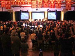
The need became evident for a road-ready system with superb pattern control, both in the mid/high range as well as the low-end. To achieve our 105 dB (A-weighted) requirement across the entire listening plane, the cabinets had to be capable of producing 138- 139 dBA at 1 meter.
In addition, the arrays had to fit within the working 1,000-pound weight limit. Because of the already high cost of the project, we couldn’t afford to add larger motors to accommodate heavier loudspeakers.
Another complication was the load-in. The gymnasium is on the second floor of the building, which means in addition to a long push down multiple hallways, the gear must be sent up (and down) via a 5-person elevator. This required the cabinets to not only be light, but small enough for four stacks to fit in a single elevator load.
Finally, the rigging had to be simple enough for a small (sometimes just two) volunteer crew to fly the arrays without needing a large amount of time or extra manpower.
Examining Options
We determined that the needs of the application could be met with “midsize” line array elements, and there are a lot of great choices in this genre.
The contenders were first evaluated on the basis of the required box count versus cost. Two of the models, with 5- and 6-degree vertical splay, required an array of seven to eight cabinets per side in order to meet the required 40 degrees of vertical coverage and target SPL.
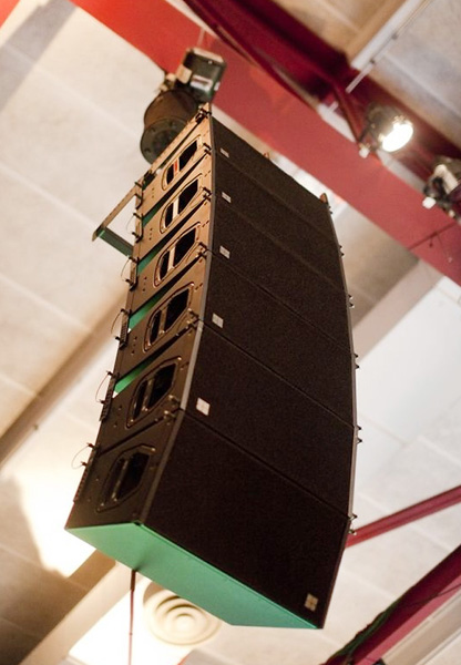
Conversely, another model under consideration – the d&b audiotechnik Q1 with a 14-degree vertical splay – required one less cabinet per side to achieve the same results. In addition, a single Q10 (40 degrees vertical x 110 degrees horizontal) could be substituted as the bottom cabinet in the array for even greater coverage in the near field.
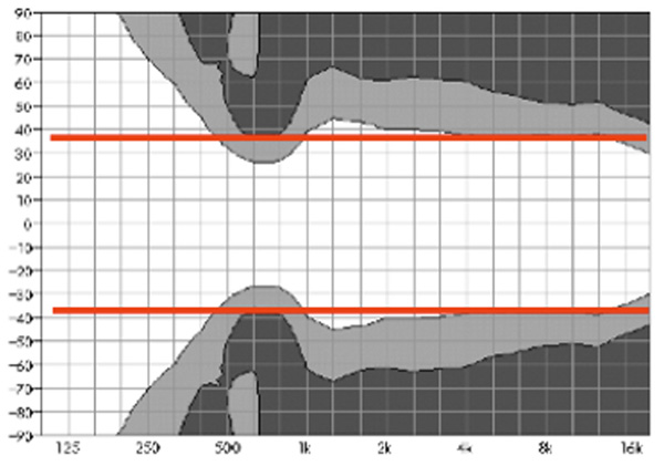
All options were then examined more closely, using isobar plots to determine their horizontal directivity (one manufacturer was unable to offer any data in this area) and how they would “behave” in the room.
In addition to the manufacturers’ prediction software, a model of the room – including all acoustic obstructions – was created in AFMG EASE for the purpose of more extensive mapping. This helped determine what the primary and secondary reflections in the diffused field would look like, as well as intelligibility. It also helped us to calculate maximum trim heights in order to fire under obstacles such as vinyl banners and retracted basketball goals.
Following this process, it was a relatively easy decision as to which model would provide the optimum solution for this specific application. In addition to the vertical splay advantage noted earlier, the d&b Q1 also weighed in at less than half of the other boxes, and exhibited far better pattern control.
It incorporates a dipolar LF driver arrangement that maintains horizontal directivity down to 400 Hz, which means dramatic reduction in the diffused field since wall reflections are primarily contained to the 75-degree horizontal pattern of the array.
All of this resulted in main left and right arrays, flown in the optimal locations according to modeling, each comprised of five Q1 elements and one Q10 element at the bottom.
In addition, much of d&b’s subwoofer line, when properly deployed, can yield the same tighter pattern control in the low frequency ranges. As a result, we decided to pair the arrays with four d&b J-Sub subwoofers, evenly spaced along 18 feet of the floor in a tight-formation horizontal array.
The J-Sub is a cardioid, triple-18-in subbass cabinet, housing two forward-firing drivers and one rear firing, with a switchable cardioid and hypercardioid pattern. When paired together, the pattern of the sub array complements that of the main arrays almost perfectly.


