

As audio professionals, the more we understand what’s under the hood of modern power amplifiers, the better we can make a wise buying decision.
What are the main sections or parts of a power amp? Every power amplifier includes a power supply, an input stage, and an output stage. Most amps also have protection mechanisms; some have DSP, and a few have networking capability.
Let’s explain each feature…
Power Supply
Basically, a power amplifier uses the input signal to modulate DC from its power supply. This supply receives 120 volts AC from the mains outlet and converts it to DC to operate the transistors, FETs and MOSFETs and so on in the amp circuitry.
Two types of power supply are analog and switching. A typical analog power supply rectifies the incoming 50 or 60 Hz AC and low-pass filters it to create DC for the power amplifier circuitry.
A switching power supply converts the incoming AC to DC, switches it on and off at an ultrasonic rate, runs those pulses through a small, lightweight transformer, then rectifies and filters the waveform to produce DC. The switch-mode supply can be smaller and lighter than the analog supply, but is more complex.
Some amps have a separate power supply for each channel so that high demands on one channel don’t affect the other. A few also have a separate power supply for the input stage, which is the part of the amplifier that does not drive the loudspeakers.
It’s important that the power supply have enough power reserve to supply power for transients or signal peaks. That happens when the supply uses big filter capacitors that store energy, and releases it when needed.
If the amp is heavily loaded down (that is, it is driving a low output impedance), the power supply voltage may drop or “sag,” causing distortion. Using a separate power supply for the input stage prevents distortion in the input stage caused by the output stage’s supply voltage sagging.
Amplifiers of very high power draw lots of current through the power cable from the AC outlet. To avoid limiting the current that can be drawn, the AC power cable has to be heavy gauge and short.
And the circuit breakers feeding the amplifier’s AC outlet need to be 20 A or higher rather than 15 A. Low-current AC outlets can prevent the amplifier from reaching its maximum power output.
Input Stage
The input stage or “front end” accepts the input signals and feeds them to the output stage to be amplified. Here you’ll find connectors that mate with the input cables.
Level controls and any plug-in modules are part of the input stage as well. The level controls do not affect the gain of the amp; rather, they affect the input sensitivity – the input voltage required to drive the amp to full power.
Turning down an amp’s level controls does not make it less powerful or reduce its wattage rating. Instead, this requires the amp to have higher input signal to drive it to full power.
Put another way, turning down the level controls reduces the level to the output stage of the power amplifier. If you send the amp a high enough signal level, you can drive the amp to its full rated power even with the level controls turned down from maximum.
In fact, it’s standard practice to set the amp’s level controls for proper gain staging. Set up the sound system’s mixer so that signals peak around 0, then gradually turn up the power amp’s level controls until the sound is as loud as you want it. This results in the best system signal-to-noise ratio and headroom.
If you turn up the amp’s level controls to maximum, you’ll often hear mixer noise through the system loudspeakers because the mixer will have to be run at levels well below 0 on its meters.
Let’s look at other parts of the input stage. LED’s on the front panel indicate signal level, clipping, and overheating, so they can be used for diagnostics if you hear no sound or distorted sound.
Connectors in the input stage are on the back panel of the amp. You’ll see these types of connectors:
• 1/4-inch phone jacks: These are most often seen in portable PA or small band PA systems. TS (tip-sleeve) is unbalanced; TRS (tip-ring-sleeve) is balanced and is preferred for its rejection of hum and noise.
• Female XLR: This three-socket locking connector mates with a male XLR and provides a balanced connection. It’s used in portable PA and touring sound applications.
• Terminal block (terminal strip, screw terminals). This type is intended for permanent installations. It lets you eliminate connectors and their cost because the input cable is hard-wired to the terminal block.
• RCA or phono connectors: These are used for background music systems and home stereos.
All XLR inputs, terminal blocks and most phone jacks are wired balanced which rejects hum and noise on the input cable.
Output Stage
This stage amplifies, or increases the power of, the input signal up to a level sufficient to drive the loudspeakers.
In this stage are the power transistors (output devices), which tend to generate a lot of heat. Also in this stage are the output connectors which are wired to the loudspeakers.
Four types of output or loudspeaker connectors are phone jacks, five-way binding posts (banana jacks), Speakon connectors and terminal blocks (screw terminals).
• Phone jacks are inexpensive connectors for low-power applications. They are often seen in portable PA systems.
• Five-way binding posts provide a temporary or permanent, high-power connection to banana plugs, spade lugs or stripped wires. You’ll find these connectors in amps for touring sound.
• Speakons are a high-power, locking, cylindrical connectors used in touring sound.
• Terminal blocks are mainly used in installed sound applications to eliminate connectors and their cost.
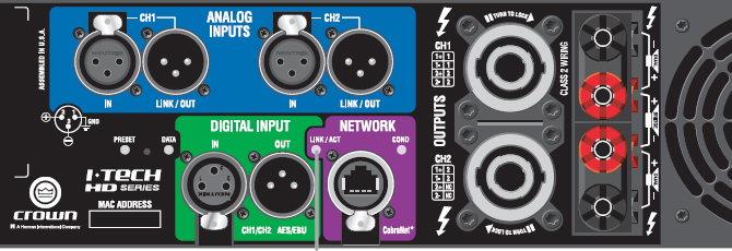
Figure 1 is the back panel of a Crown I-Tech HD power amplifier, showing XLR, Speakon and five-way binding post connectors.
The best power connectors have low contact resistance. As contact pressure and contact area increase, contact resistance goes down. High-pressure contacts increase current flow by helping the current to penetrate through the surface films. They also increase contact area by flattening out the contact surfaces.
So when you use banana plugs, it helps to “stretch out” the ribs in each pin to increase contact pressure. Use a small screwdriver to bend the ribs.
Protection
The better power amps include circuitry that protects the loudspeakers and the amp itself from overheating and burning out. Some include a limiter to prevent the output power from getting too high and causing clipping, which can destroy tweeters.
Others prevent DC and ultrasonic signals from reaching the loudspeakers in the event of amp failure. Low-end units just blow a fuse or trip a circuit breaker if the current draw is too high, while high-end amps limit the output power so that the music doesn’t stop.
Cooling
The main cause of amplifier failure is overheating, so most amps include heatsinks and fans to keep the amp cool. In some units the fans come on only when needed. Some Class D amps tend not to get hot, so they don’t need fans.
DSP
Many models include built-in digital signal processing: compression, limiting, EQ, filtering, and so on. The advantages are:
• There is less gear to lug around in racks.
• EQ and limiting presets can be set up in DSP to work with specific loudspeaker models. Just select a preset that works with your chosen speakers.
• Some DSP includes diagnostics such as load monitoring to check for blown speakers, error logging, and so on.
Networking
Another feature in many modern amps is networking. Network-capable amps can be part of an interconnected audio network, so they can be controlled and monitored from a central computer. This beats walking around on stage trying to figure out which amp has shut down.
Amplifier Class
Let’s turn now to another aspect of power amplifier design. Amplifier class refers to the circuit design of the output stage, such as Class A, Class AB, Class D, and so on.
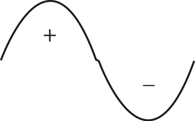
As a background for this section, remember than an audio signal has a positive half of the cycle and a negative half of the cycle (Figure 2).
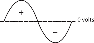
Transistors are basically rectifiers; they can conduct (pass current) only during the positive or negative half unless they are biased by a certain amount. The bias can create a DC offset in the signal.
Here are the features of the most common classes:
Class A
• Has enough bias (DC offset) to shift all of the audio signal into the positive region in the output devices (Figure 3). As a result, positive/negative signal halves become more positive/less positive changes.
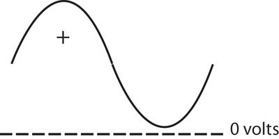
• Because the output transistors are always on, current flows at all times. This design generates a lot of heat. Some power is dissipated even when there is no music playing.
• Lowest distortion.
• Least efficient (typically 20 percent); wastes a lot of energy.
• Typically used in audiophile applications up to 300 W per channel.
Class B
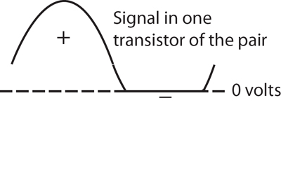
• The output devices are in push-pull pairs: one device amplifies the positive half of the sine wave signal, and the other amplifies the negative half. Each device of the pair is on for half of the signal cycle (positive or negative voltage) and off for the other half of the cycle. Each device conducts for a half cycle.
• Much more efficient than Class A (typically 60-70 percent).
• Less heat.
• There is discontinuity at the transition point between transistor signals near 0 volts (Figure 4). This results in high “crossover distortion” or “switching distortion” – low sound quality.
• Typically used for pocket radios or clock radios.
Class AB
• Both output devices in each pair are biased slightly on which reduces crossover distortion. Each transistor operates slightly more than half the cycle but is off for a fairly long time, which reduces heat dissipation. (Figure 5).
• About 50 percent efficiency.
• Low distortion.
• Typically used for home stereos and pro audio amps up to 600 W per channel.
Class G or H
• Both of these classes include two DC rails (DC supplies) of low voltage and high voltage. The high-voltage rail is switched on only when the input signal demands it, which reduces the amount of heat in the output devices. The power supply is signal-controlled.
• In Class G, one output stage is fed by the low voltage rails and another stage is fed by the high-voltage rails. The low-voltage stage is always on, and the high-voltage stage turns on only when the signal exceeds a threshold level. Class H uses only one output device stage which is fed variable supply voltages depending on the amplitude of the signal.
• Fewer output devices and less heat sinking are required, which reduces the weight and size of the amp.
• Tends to have elevated distortion at high frequencies due to the switching.
• Typically used for LF or MF applications from 400 to 3000 W per channel.
.Class D
While the other classes operate in a linear (analog amplifier) mode, Class D amplifiers run the output devices as switches (on or off) at an ultrasonic frequency to create a continuous series of square waves or pulses.
The input signal is made to modulate the pulse width, an operating principle called pulse width modulation. The pulses’ high frequencies are filtered out, and this filtered output (an analog signal) drives the loudspeaker.
• Very efficient (90-95 percent). That’s because the transistors are either on (with high current and no voltage) or off (with high voltage but no current). So there is very low power dissipation compared to linear amplifiers.
• Tends to be small and light because of less cooling and fewer output devices.
• Typically used for high-power car stereos and pro applications where heat, weight and size are considerations.
Class I
• Class I or BCA (Balanced Current Amplifier) design developed by Crown is an efficient system based on Class D switching amplifier technology. The amp needs only a little AC power to operate.
• According to the manufacturer, a BCA amp generates one-tenth the heat of conventional amplifiers so it can work with much less air movement. This reduces fan noise, heatsink size, filter maintenance, and failure due to heat, so the amp can be small and light.
• A BCA amp re-uses the energy returned from the speaker rather than dissipating it as heat or forcing the amp into premature current-limiting. This helps BCA models handle 2-ohm loads without shutting down.
I hope we’ve clarified some of the differences among power amplifiers. They are another component in the chain of audio equipment that we need to understand well.