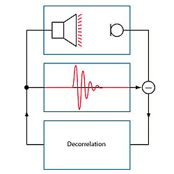
The zero degree phase locations repeat every 360 degrees of phase change.
For a linear phase transfer function you can calculate the frequency spacing of potential feedback locations as a function of delay time. The equation for calculating the delay time is:
Delay Time (sec) = -ΔPhase / (ΔFrequency x 360)
When ΔPhase = 360 degrees (the phase difference between two 0 degree phase locations), this leaves:
ΔFrequency = 1 / Delay Time (sec)
when ΔPhase is 360 degrees
This means that the potential feedback frequency spacing = 1 / delay time (in seconds). The following shows the potential feedback frequency spacing for various delays.
• 1 / 0.002 sec. = 500 Hz spacing (for 2 ms of delay)
• 1 / 0.010 sec. = 100 Hz spacing (for 10 ms of delay, shown below)
• 1 / 0.1 sec. = 10 Hz spacing (for 100 ms of delay)
This implies that adding delay makes the potential for feedback worse (i.e. there are more potential feedback frequencies because they are closer together).
Practical experience will tell you otherwise. This is because delay also affects the rate at which feedback grows and decays. If you have 10 ms of delay between the microphone and loudspeaker and +0.5 dB of transfer function gain at a potential feedback frequency, then feedback will grow at a rate of 0.5 dB / 10 ms or +50 dB / second. If you increase the delay to 100 ms then the growth rate slows to +5 dB / second.
Here is another observation regarding gain and its relationship to feedback: For a fixed delay you can calculate the growth rate of a feedback component if you know how far above unity gain the open-loop system is at a particular feedback frequency.
This means that if you are at a venue and can hear feedback growing (and can estimate its growth rate) you can calculate roughly how far above unity gain the system is (this also means your kids probably call you a nerd).
As an example if you estimate that feedback is growing at a rate of 6 dB / second and you know that the distance from the loudspeaker to microphone is 15 feet then you know that the gain is roughly only (6 x 0.015) or 0.09 dB above unity gain. So… you only need to pull back the gain by that amount to bring things back into stability.
Of course the rate of change also applies to feedback as it decays. If you pull the gain back by 0.09 dB the feedback will stop growing. If you pull back the gain by 0.2 dB then the feedback frequency will decay at close to the same rate that it was growing. If you reduce the gain by 3 dB (below the stability point of unity) it will decay at a rate of 200 dB / second.
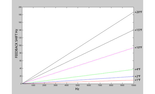
Note also that anything that changes phase will affect the feedback frequency locations. This includes temperature changes as well as any filtering and delay changes. If you analyze how temperature changes affect the speed of sound and look at the corresponding effective delay change that a temperature shift yields, you end up with an interesting graph.
Figure 3 shows the shift of a feedback frequency based solely on how temperature affects the speed of sound. The interesting points are that feedback frequency shifts are larger at higher frequencies and the potential for feedback frequency shifts could be significant (depending on your method of control), but more on this later.
To summarize:
• Feedback is both a magnitude and phase issue.
• Increasing system delay, increases the number and reduces the spacing, of potential feedback frequencies.
• Delay also affects the rate at which a feedback frequency grows or decays.
• To bring a runaway feedback frequency back into control you simply need to reduce the gain below unity. However, it will decay at a rate based on its attenuation and delay time.
• Temperature changes (and anything else that affects phase) affect the location of feedback frequencies.

