You’ve just acquired a 3-D, FFT-based measurement system and are ready to use it to tune a sound system. (Oh, you haven’t? Then click here to learn more.) Now let’s get to it!
The first thing to do is place the calibrated measurement microphone on a mic stand in the middle of the listening area, turn on all of the system’s loudspeakers and turn up the test signal, just as is done with a real-time analyzer (RTA). Right? Sorry—wrong!
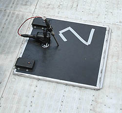
First, putting the mic on a common mic stand can unnecessarily contaminate the FFT (Fast Fourier Transform) measurement. That hard reflection off the floor is a non-minimum-phase, delayed source whose effect cannot be equalized.
When making (Rational Acoustics) Smaart and (Meyer Sound) SIM measurements, the mic should be laid in a pressure zone (PZM) position directly on the floor. This will remove the comb-filtering effects of the reflection from the measurement.
If using (Gold-Line) TEF, it’s acceptable to put the mic on a light stand to get it away from the floor so that the reflection is delayed enough to be “windowed” out of the measurement time limits.
Low-frequency response of the measurement will also be limited, but room modes render low-frequency measurements within a room and far from the loudspeaker(s) useless anyway. (More on this later.)
Be aware that any hard, reflective surfaces near loudspeakers will also cause the same types of problems. Either move and aim the loudspeakers to avoid creating these reflections, or treat the surface with absorption to prevent them.
Otherwise, a comb filter (Figure 1) will color the source’s tonal quality for most listening positions for a given loudspeaker in a system. Because 3-D measurements are time-sensitive, other loudspeakers can cause comb-filter contamination just like reflections. Therefore, they must be eliminated from the measurement. (See Figure 1 again!)
That’s right, you need to be equalizing for a flat, direct response on-axis to just one loudspeaker per crossover-bandpass section.
Where long wavelengths combine, such as with subwoofers and the low-end of the low-mid loudspeaker frequencies, further consideration is needed. And for mid-highs, this is a hard and fast rule. Any other frequency-response problems—such as lack of high-frequency level at listening positions off-axis or between cabinets—are issues of inadequate coverage, not equalization.
Because we’re equalizing loudspeakers and not rooms, particularly at short wavelengths, separate EQ is needed for each type of loudspeaker. One equalizer cannot be tuned correctly if it’s feeding multiple types of loudspeakers. Again, dedicated EQ and amplifier signal path for each type of loudspeaker is required.
For example, take a loudspeaker cabinet loaded with double 12-inch or 15-inch woofers. The measurement microphone—during EQ—must be positioned exactly between the two drivers, so that the path-length from each are close enough to not have any cancellations at the frequencies that the drivers are reproducing.


