
A common task in “audioland” is the need to feed a number of inputs from a single signal source. This may include driving a rack of amplifiers, providing feeds to the press, or distributing a signal around a building or campus.
The methods used to accomplish this range from the profoundly simple to quite complex, and the appropriate method can only be determined after sizing up the situation.
Impedance matching means that an output is terminated with a “mirror” input impedance. This configuration yields maximum power transfer, and more importantly, reduces reflections from a load back to the source.
In multimedia systems, the matched interface is used for very high frequency signals. These include video, antenna and digital interfaces.
One drawback of the matched interface is that active or passive splitters must be used if the source must drive multiple inputs. Otherwise the impedance match is violated and problems result.
One of the most common mistakes in audio is to attempt to apply this interfacing method to the basic analog interfaces that dominate today’s sound reinforcement systems.
In a constant voltage interface, an electronic signal source with a low source impedance (i.e. an output) is used to develop a signal voltage across a high load impedance. The minimum ratio between the source Z and load Z is one order of magnitude (1:10).
This scheme is used universally in the audio industry for passing signals from component to component. One utility of this interface is that it provides the possibility of driving multiple parallel loads from a single source without additional hardware.
The stipulations are as follows:
—The parallel combination of all loads cannot violate the 1:10 minimum impedance ratio.
—The path length (interconnecting cable) must be short when compared to the wavelength of the highest frequency component of the signal.
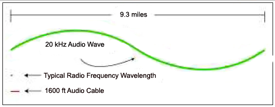
Because the speed of propagation of electricity approaches the speed of light, and audio cables are typically less than a few hundred feet, the second condition is easily met in the bulk of audio applications.
Radio frequency, digital, and video signal wavelengths are much shorter, and the impedance-matched interface must be used in lieu of the constant voltage interface to prevent signal degradation. (Figure 1)
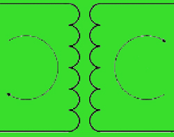
“Y” TO THE RESCUE
Figure 2 below shows an equivalent circuit of a single source driving multiple loads. Note that even though the load impedances are not the same, this is a parallel circuit so all of the inputs have the same voltage impressed across them.