When traveling to different time zones, we need to correct our time-keeping tools in order to align our activities to the local standard time. Very simple.
Likewise in sound reinforcement systems, we often encounter multiple sources of misalignment, albeit in much smaller time increments. The importance of these misalignments is often subject to debate, but with the advent of a wide variety of very good digital processing products, correcting such anomalies is no longer out of reach for most of us.
Further, the presence of affordable, accurate time-based measurement systems (Smaart, etc.) means that it is by no means impractical to clearly determine the presence of multiple arrivals from a sound system.
Almost all sources of misalignment are based on the physical positioning of various transducers in relation to one another, to their surrounding physical boundaries, and to sound sources. The only place where there are no appreciable time-based alignment problems (other than phase response) is in a sound system’s electrical signal path. The electrons that constitute electrical signals utilized in audio systems travel at close to the speed of light, and even when there are great variations in cable length or multiple stages of audio processing, the degree of leading or lagging across the audio spectrum is not perceptible to human hearing.
We focus on the transducers used for inputs and outputs when discussing misalignment. Although there is a potential for microphones (or mic technique) to be just as much a culprit as loudspeakers, traditionally we have not had the means to treat separate inputs nearly as easily as we do the outputs feeding into the loudspeakers.
Driver Misalignment. In loudspeakers with both high- and low-frequency transducers that are direct radiating (not very common in sound reinforcement), there will be offset in the arrival times of the high-frequency transducer versus the low-frequency transducer. This is simply due to their required physical positioning.
A high-frequency transducer consists of a smaller diaphragm with a shallower motor structure than its low-frequency counterpart. When these drivers are positioned on a flat baffle (the most common baffle shape) the high-frequency signals arrive at the ears of listeners sooner than the low frequency signals, on the order of several hundred microseconds (Illustration 1).
This misalignment is reversed when the high-frequency driver is horn loaded (the more common method used in sound reinforcement loudspeaker systems), requiring a waveguide of a certain depth to achieve the needed pattern control. This is one of two primary reasons for using such horns; the other reason is an increase in acoustic efficiency. With horns, high frequencies no longer lead low frequencies, but rather they lag behind, again on the order of several hundred microseconds (Illustration 2).
In loudspeaker systems where high-, mid- and/or low-frequency components are in various configurations of direct radiating and/or horn loading, it is almost impossible to realize horn lengths that position the drivers in physical alignment to one another (Illustrations 3A and 3B).
Note that the alignment of multiple drivers is not as simple as visualizing or physically measuring the location of each component’s diaphragm and then either positioning them to be in the same physical plane or applying electrical signal delay to the leading component. Every driver has varying points of acoustic origin that shift with frequency. The point of acoustic origin, as applied to driver alignment, must be measured to be derive a mean value.
Inter-Cluster Misalignment. In multiple-component loudspeaker clusters constructed of self-contained loudspeakers (two-way, three-way, etc.) or individual drivers and horns, there is another source of misalignment not always acknowledged and/or often confused by marketing hype.
All loudspeakers provide varying degrees of directivity or pattern control. But what is often referred to as a “so-many-degrees by so-many-degrees” loudspeaker can only provide this stated coverage pattern within the frequency range that is within the pattern control provided by the high-frequency horn, and to a lesser extent, the shape of the low-frequency cone driver.
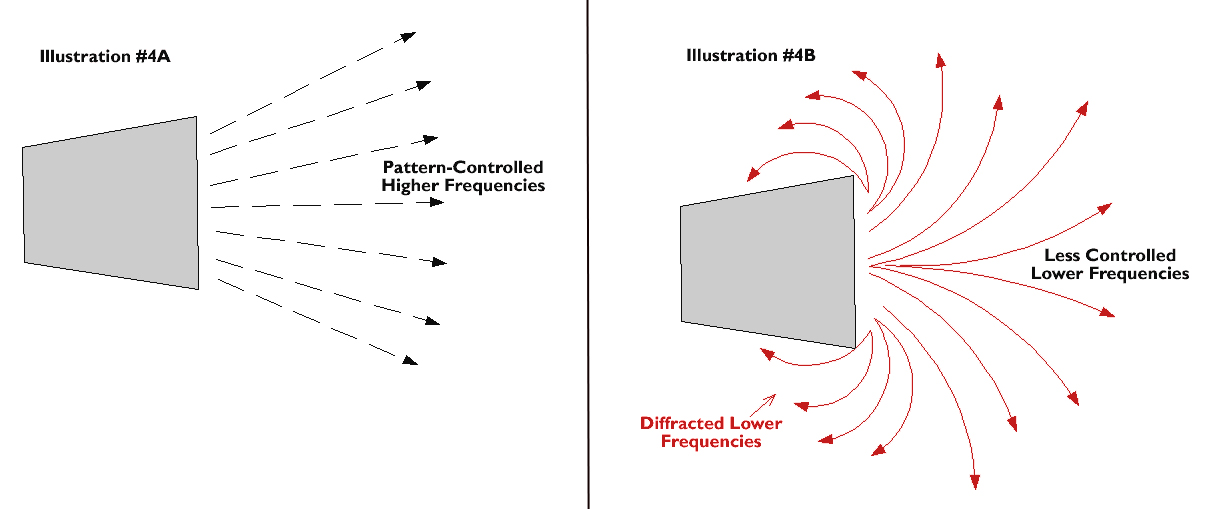
In many designs, the direct radiating woofer provides pattern control that extends from the crossover point down to the frequency range where the wavelengths become longer than the size and shape of the low-frequency cone. The result is that the specified pattern control occurs, at best, within the upper five octaves of the total of eight octaves of output supplied by typical two-way “full-range” loudspeakers (Illustrations 4A and 4B).
Thus any cluster consisting of multiple devices covering the same frequency range will have an overlap of coverage. In a well-designed cluster, mid and high frequencies will not overlap significantly. But even a very well designed cluster, using premium loudspeakers, will present overlap at lower frequencies.
Within the coverage zone of one loudspeaker, overlapping output from one or more neighboring loudspeakers will arrive slightly later. The resulting combined coverage will be altered due to comb filtering, also known as destructive interference. However, during the process of loudspeaker system optimization, it is often possible to delay one loudspeaker in relation to another in order to minimize this interaction within the primary coverage zone.
Part of this optimization process includes observation of the effects of such delay on each loudspeaker’s coverage. As delay is applied to a loudspeaker to optimize the response of its neighbor, it is important to insure that the response of the primary loudspeaker (providing primary coverage in its zone) has not been worsened.
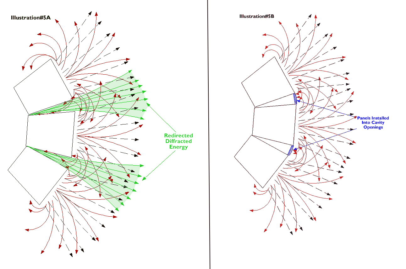
Another source of time-based signal corruption is the diffraction that occurs at lower frequencies. These longer wavelengths literally “wrap around” a loudspeaker enclosure, and in clusters consisting of several splayed loudspeakers, this diffracted energy enters the cavities between the enclosures and is re-projected back out towards the primary listening area (Illustration 5A).
The interference that results from the combining direct energy with diffracted and redirected energy (that is now lagging behind) can result in severe dips in the lower-mid frequency range.
The size and shape of these dips is dependent on the physical dimensions of the loudspeaker enclosure. This anomaly cannot be equalized nor can it be corrected with delay, but fortunately, it can be treated physically by inserting appropriate panels that close off the openings to the cavities (Illustration 5B).
Architectural Boundaries. A potential source of destructive interference can exist outside of the loudspeakers or clusters themselves, within the physical boundaries of a given space. If loudspeakers are placed close to room boundaries (walls, floor or ceiling), there is interaction that results in interference patterns. This varies across the frequency spectrum.
At low frequencies, there is reinforcement (boost) caused by boundaries, causing an increase (sometimes desired) in low-frequency levels.
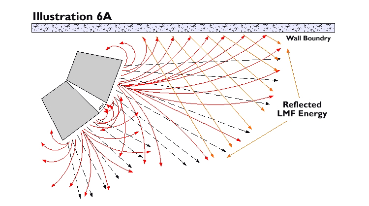
At mid frequencies, some points in the spectrum also are increased due to reflection, but many other points are impacted by cancellation caused by reflected sound combining with the loudspeaker’s direct output (Illustration 6A).
At high frequencies, there is very little (or no) effect, because these frequencies are well controlled and projected forward, away from nearby boundaries.
Often we’re forced to place a cluster or fill loudspeaker in front of the proscenium walls surrounding a stage, with the resulting frequency response altered, primarily at mid frequencies. Lows are largely unaffected (because they are long enough to wrap around the proscenium) and highs, much more controlled and directed outwards, are hardly affected at all.
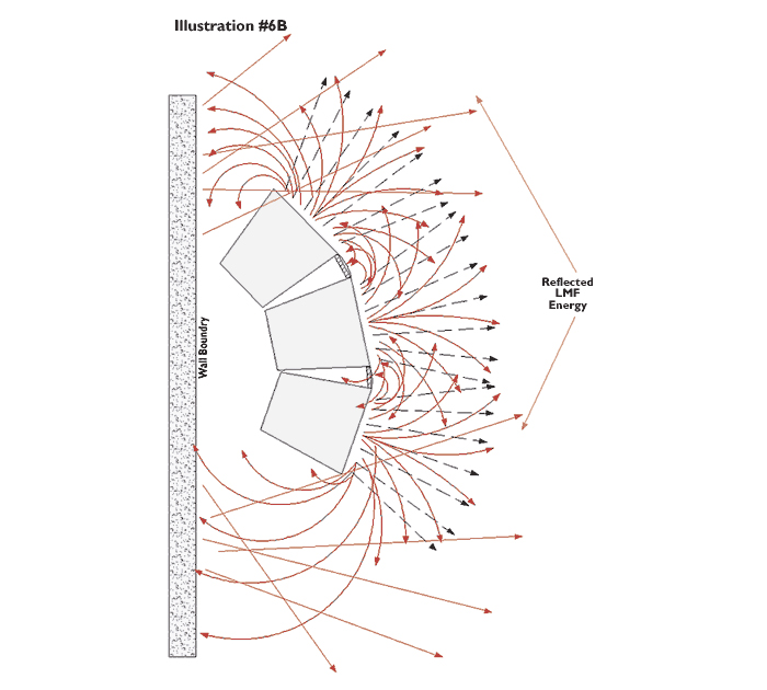
But at lower-middle frequencies, where the wavelengths are long enough, stray energy will wrap around (diffract) the enclosure, reflect off the proscenium wall and combine with direct energy coming from the loudspeaker (Illustration 6B). Again, the primary culprit is the reflected energy lagging behind the direct energy, and again, this cannot be corrected other than by removing the source of reflection, usually moving the loudspeakers away from the boundaries.
In recording studios it has long been common practice to soffit-mount large-format monitor loudspeakers into the front walls of the control room. In doing so, diffraction induced anamolies are minimized, and low-frequency boundary reinforcement is maximized.
The same technique can be applied to installed reinforcement systems as long as proper architectural positions are available. And, it takes confidence on the part of the system designer, confidence in choosing the correct positions and that loudspeakers won’t have to be moved.
In designing and building soffits (or closets as they’re sometimes called), it’s imperative that the cavities behind the loudspeakers are closed off, made to be acoustically benign. Further, loudspeakers must be anchored so they do not vibrate or move, and also, convenient access for service should be planned. Finally, there can be no obstruction to direct energy emanating from the front of the loudspeakers. To this end, it is wise to remove the factory grill so that sound must only pass through the grill installed to conceal the soffit opening.

