

Crossover networks are not unique to audio and acoustics. The role of such a network is to produce a transition between two systems of differing capabilities.
In a loudspeaker system, an increased overall bandwidth is achieved by splicing together two or more lower bandwidth transducer responses. An individual woofer, squawker and tweeter can form a full-range system through the use of a crossover network.
Let’s look at some other systems that require similar transitions between their individual components.
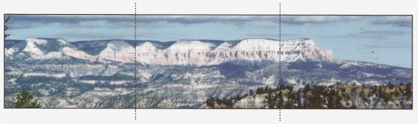
Several photographs can be combined to form a panoramic view of a landscape that is too wide for a single shot (Figure 1, below). A seamless transition is required to preserve the realism of the image.
An automotive transmission is an example of a mechanical crossover network. The wheels must rotate at increasing speed for the car to go faster.
The rotation of the engine is transferred to the wheels via the transmission. Low gears are required to get the car rolling, while higher gears allow the same rotational speed of the engine to produce higher speeds from the car.
A well-designed transmission allows the automobile’s speed to increase without discernable discontinuities as the gears shift.
In a loudspeaker system, a similar transition is necessary. The definition of frequency is “the rate of phase rotation.” As frequency increases, the rate of phase rotation also increases.
The bandwidth of a loudspeaker describes the range of frequencies that can be transduced into sound with reasonable accuracy. A single transducer does not have sufficient bandwidth to reproduce the frequency range that humans can hear, so multiples must be “stitched” together using crossover networks.
The crossover network in a loudspeaker system has the same job as the transmission in an automobile – to provide a smooth transition between elements of differing rates of phase rotation. I
n an automobile, if the phase relationship between the gears is not correct (they are mis-synchronized), the transmission jerks and service is required. In a loudspeaker, phase discontinuities at crossover points produce inaccuracies in the reproduced sound.
RUNNING THE RACE
Anyone who has watched a relay race in a track and field competition will quickly realize that the hand-off of the baton is one of the most critical aspects of the race. Relay teams practice for countless hours to develop a good transition. Even though two consecutive runners have different speed capabilities, during the hand-off their speeds must match precisely.
In all of the transition examples mentioned, the workload is being shifted from one system to another. Through the transition region, the role of one element is diminishing as the role of the other is increasing.
It is not possible or desirous to produce an instantaneous transition – such as one runner stopping completely to hand the baton to a stationary runner that must then accelerate to keep the race going.
Such an abrupt transition would take much longer than a smooth hand off between runners of equal speed.
The same principles are at work in a loudspeaker crossover network. The steeper the filter slopes are made (or, in other words, the more abrupt the transition from one to the next), the more delay there is through the transition region (Figure 2).
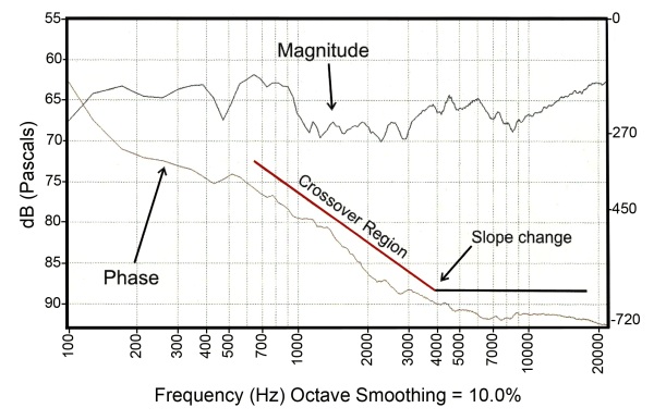
The filter order describes how abruptly sound changes in level between the passband and stopband.
Steeper slopes require more circuitry, which in turn means more delay through the transition region.
Less delay is produced if the transducer’s responses have more overlap in their energy contribution to the overall response (lower order filters).
In a relay race, the length of the hand off region (overlap) must be controlled to minimize distance over which both runners are running the race.
Too great an overlap region will fatigue both runners.
In a loudspeaker, too great a crossover region can produce undue stress on the individual loudspeaker components (due to excess bandwidth) and a loss of fidelity (due to phase interference between the transducers).
THEORETICAL VS REAL WORLD
Figure 3 shows the most common method of displaying the magnitude and phase response of a crossover network. The individual filter sections here exhibit the phase shift that would be expected from observing the magnitude response (i.e., they are minimum phase).
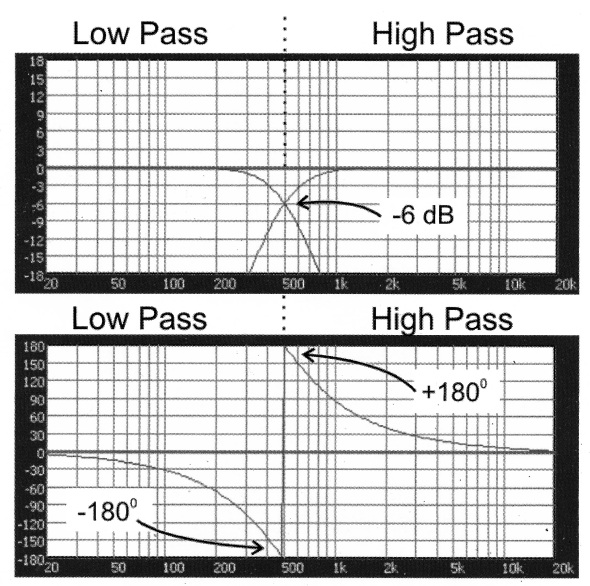
When the filters are summed (whether electronically or acoustically via radiation from loudspeakers) the magnitude response remains “flat” but the phase response exhibits the effects of passing through the filters.
A “perfect” loudspeaker would have infinite bandwidth and no frequency-dependent phase shift.
If each frequency were represented by a rotating phasor of equal length (each spinning like a propeller), a snapshot made at the time the slowest phasor (lowest frequency) went though 0 degrees would find that all of the other phasors were lined up with it (Figure 4).

For the band-limited case, the high and low pass responses would have a lagging and leading phase angle respectively if the snapshot were taken when the center frequency of the bandwidth went through zero degrees (Figure 5).

A real-world crossover network using steeper filter slopes to produce a sharper transition would yield significantly more phase shift through the crossover region, even though the high and low pass might be in-phase at the crossover frequency (Figure 6).

The polar graph can be viewed three-dimensionally to get an improved perspective on what is happening through the crossover region (the Heyser Spiral, Figure 7).
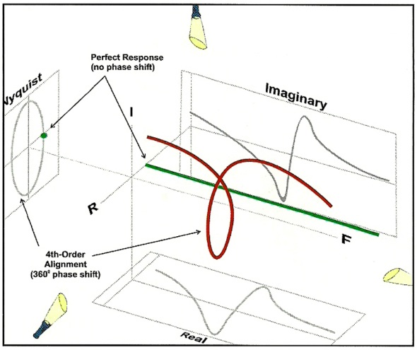
Figures 4, 7, and 8 show the electrical magnitude and phase response of a common crossover topology – the 4th-order Linkwitz-Riley.
Note that both the high pass and low pass magnitude responses are down 6 dB at the crossover frequency.
Also note that the relative phase difference at the crossover frequency is 360 degrees which means that the two sections will sum coherently to 0 dB.
Therefore this alignment produces a flat magnitude response through the crossover region.
The phase response exhibits the effect of the filters, with the phase angle becoming increasingly negative with increasing frequency.


