The end fire array is one of the most talked about – even if not the most often implemented – of the cardioid subwoofer arrays.
It can be a challenge to wrap our heads around how we get the loudspeakers to play leap-frog in the forward direction and demolition derby on the back side.
Looking at the loudspeakers from a coverage angle point of view is a non-starter. They are omnidirectional. How do you add 360 degrees and 360 degrees?
Driven By Phase
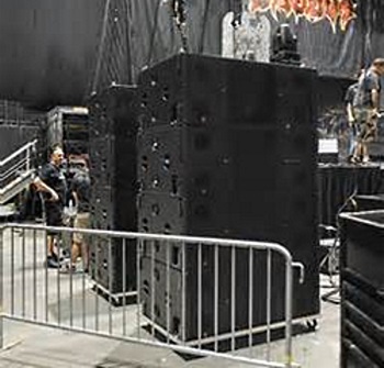
End fire defined: “A line array of emitters (in our case: loudspeakers) that are spaced and time-sequenced to provide in-phase addition on the forward side and out-of-phase rejection on the rear. The timing is set to compensate for the displacement between the sources in the forward direction. The most forward element is delay the most, and sequentially less as we approach the last element.”
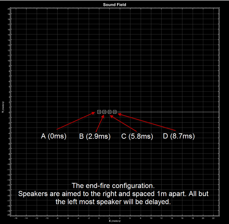
In our discussion here, we’ll use four elements (more or less can be used – more makes it more directional) and space them 1 meter apart. The delay required will be multiples of 2.9 milliseconds to sync them in front. The physical setup is found in Figure 1.
The next thing to view is the individual radiation character of a single element in our frequency range of interest. The Meyer Sound MAPP plots are 1/12-octave, which might seem severe for an omnidirectional loudspeaker, but we must use high resolution to see the driving action of phase as we progress.
Think about the fact that an octave resolution plot incorporates a 2:1 range of wavelength. In order for us to clearly see the driving effect of phase, we can’t have a 2:1 slop in the data.
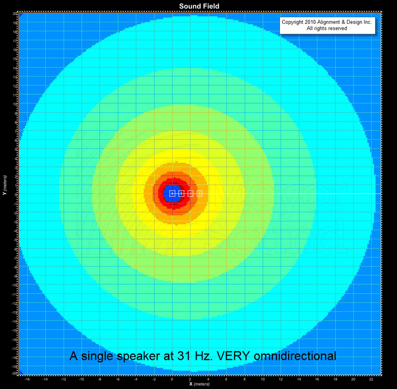
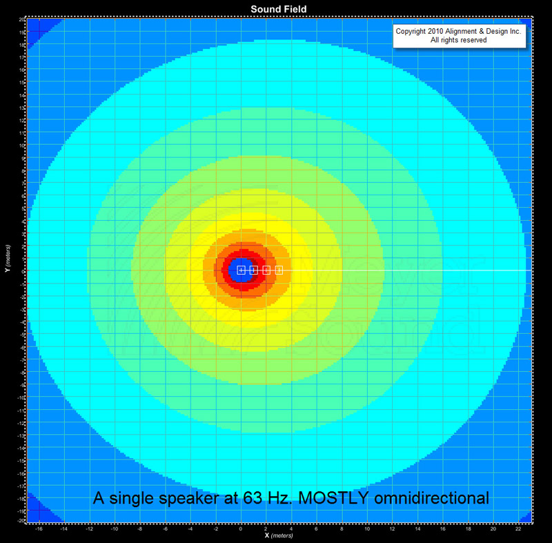
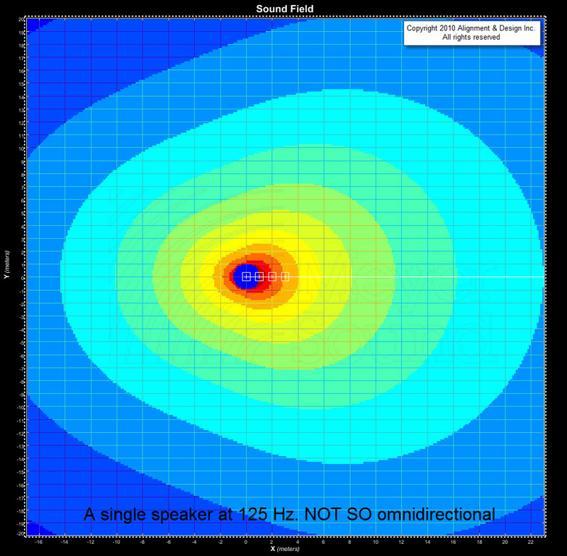
What you see in Figures 2, 3 and 4 is the decreasing omnidirectional nature as we rise in frequency. This means that as frequency rises, we’ll have both level and phase steering controls. At the bottom, only the phase lever will be operational.
The Unfinished Product
Next we look at what could have been. What would the response be if we spaced the elements in a 1-meter line (facing to the right) without the sequential delay taps? We could call it the end-no-fire array or the begin-fire. (You choose.)

The reason to do this is to see where the amplitude goes. The answer: it follows the phase. Let’s look now at the 31 Hz response in Figure 5a. We see the phase wavelengths laid on to the empty MAPP plot. If the loudspeakers are 100 percent omnidirectional, this is all we need to know to see where the sound will go.
The location where the lines cross is where they’re in phase. The fronts of the loudspeakers are pointed to the right, but by sleight of phase, we’ve magically moved the main lobe up and down.
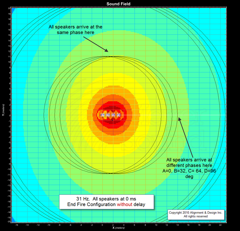
Figure 5b shows the combined response of the four loudspeakers, and indeed the strongest sound is heading north and south. However, the steering is not extreme. Why? The answer, again, is in the phase. The loudspeakers are sequentially only 32 degrees apart (2.9 ms and 31 Hz).
The response in the left and right directions don’t fall all the way out of phase – no 180-degree type of differentials. Therefore, the relationship between the elements is more like a lack of cooperation than a serious fight.
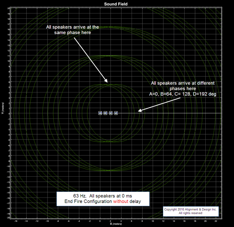

As we rise is frequency to 63 Hz (Figures 6a and 6b), the wavelength is cut in half. The displacement (1 m) is still the same but the phase shift is now 64 degrees per element. By the fourth element we’ve reached 192 degrees of phase shift. The first and fourth elements are in full conflict.
The result can be seen in the squeezing of the sides in favor of up and down. where all four elements are 100 percent in phase. As we move around the circle (from the top) we can see the lines gradually moving apart. This coincides with the gradual loss of level as we move to the sides.

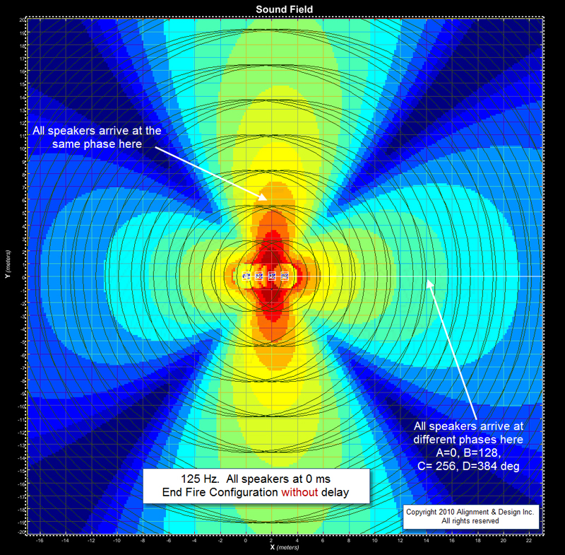
Next up is 125 Hz (Figures 7a and 7b). Once again the wavelengths shrink in half. Now we find ourselves with the four loudspeakers lapping each other on the sides and spreading out evenly in the corners. The full laps create addition on the sides – mixed with the loudspeakers that are not in phase – creating a push/pull situation. This is how side lobes are built. On the diagonals we see the deepest cancellations, due to four evenly spread arrivals.
With Delay
Now let’s add delay to the array. What happens is that part of the cycle elapses inside the electronics (the delay) and this means that the cycle completes its first turn at a shorter distance from the loudspeaker. From then on it turns again at the normal distance relative to its wavelength.

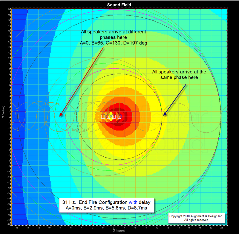
In our first look (Figures 8a and 8b) we will see 31 Hz. The four loudspeakers all arrive in phase at the right side (in front of the loudspeakers). Each travels a different distance, but each has a different electronic head start. The result is that they all finish their first lap at the same spot and then go forward from there.
On the back side, the electronic head start still applies – but the physical head start is reversed. The result now is that the phase responses fall more quickly apart, such that loudspeakers A and D are 197 degrees apart. Big time cancellation.

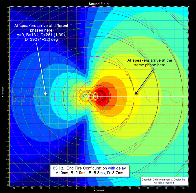
Figures 9a and 9b show 63 Hz. The same thing happens in front, but now the back side is spread by more than a full lap. The sides (top and bottom of the screen) gradually fall apart as we move from front to back, creating the incremental steering that concentrated energy forward and rejects it rearward. The mechanism is laid bare here – where the lines converge is where we see the energy, and where they spread we see blue.

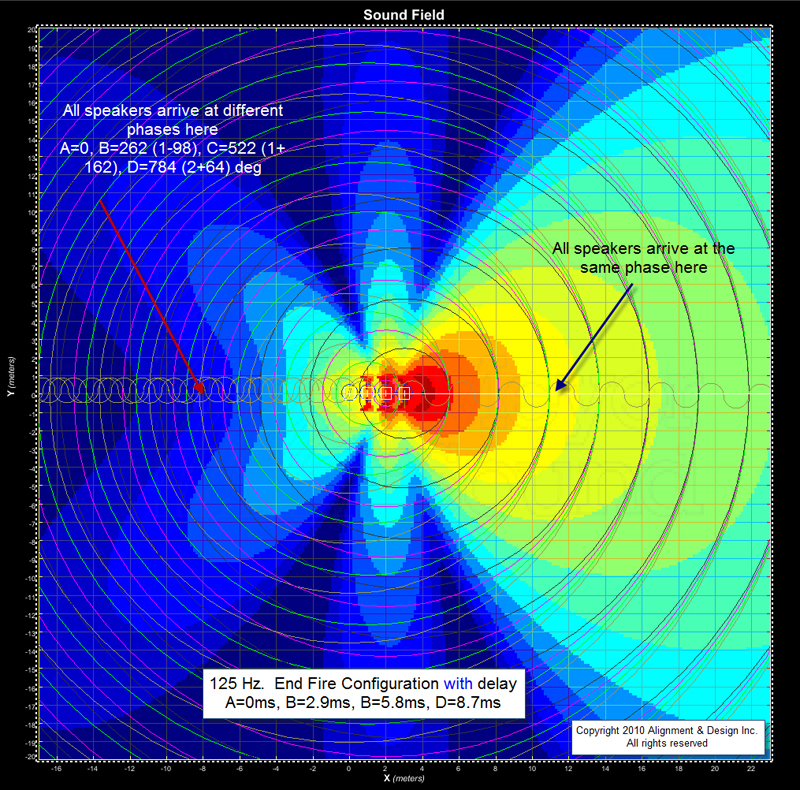
By the time we reach 125 Hz (Figures 10a and 10b), we’re turning multiple laps on the back side and even on the sides (hence the side lobes). There’s also a small component of directionality of the loudspeakers here.
Hopefully this graphics-based presentation helps clarify some of the mysteries of the end fire sub array.


