Let’s pause briefly here and address why loudspeakers exhibit phase shift to begin with.
By means of mechanical-electrical analogies, properties like friction, mass and stiffness (compliance) can be modeled in RLC circuits using resistors (“R”), inductors (“L”) and capacitors (“C”), of which transfer functions can be calculated and measured.
In the case of vented enclosures (Figure 4, Left), the enclosure design alone (wood, screws and glue) will typically cause fourth-order high-pass filter behavior, including the inherent 360 degrees of phase shift, at the tuning frequency where port and direct radiator resonate. No electronics involved!
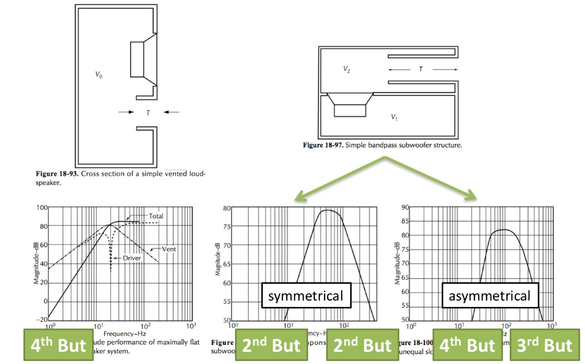
The vent (or port), however, is a double-edged sword. It extends low frequencies but at the same time enables the driver to “breathe” through the port, which until somebody bored a hole in the baffle was more challenging (trapped air – bicycle pump). Therefore, a subsonic electronic high-pass filter to prevent over-excursion (Figure 5, Row 2) or an alternative means of loudspeaker protection becomes mandatory.
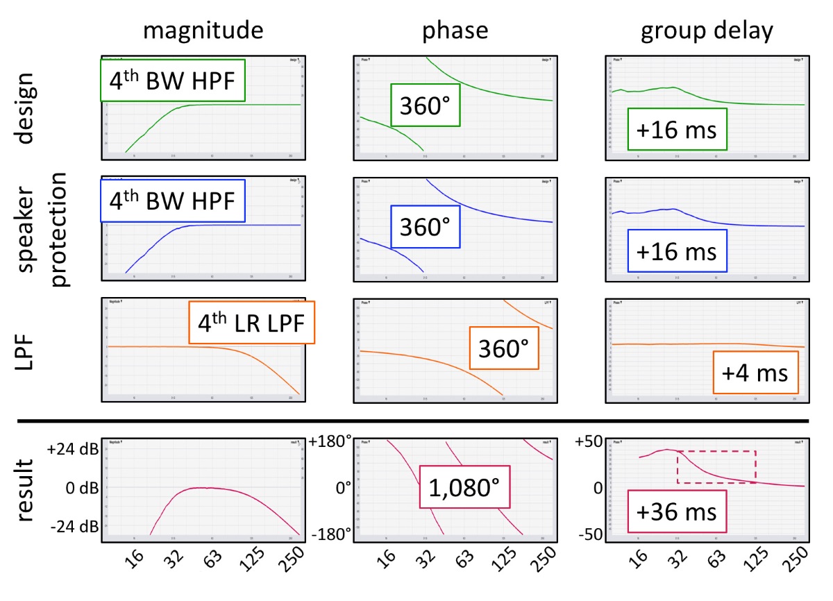
To conclude this example, the subwoofer’s bandwidth needs to be reduced to the intended range of operation. For vented enclosures (unlike band-pass designs), this is typically achieved by means of an electronic low-pass filter (Figure 5, Row 3).
Upon completion, the compound phase shift typically equals three cycles (1,080 degrees) or more, throughout a mere 2-octave wide interval (Figure 5, Row 4)!
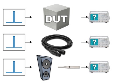
This accumulated phase shift prohibits loudspeakers from acting like microphone cables, which are free from any phase shift. And everybody wonders why a subwoofer is typically incapable of delivering more than a single frequency at a time?