
This is the third in a multi-part series. Additional segments are available here.
Previously we examined the basics of cardioid subwoofer systems. These examples continue that series.
Example 2. “Measurements on a real system: two facing forward and one backward”
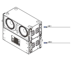
In this example our cardioid configuration uses three stacked DAS LX218A subwoofers. The top and bottom ones are facing forward while the centre one is firing backward.
The DAS LX218A subwoofer is a self-powered system incorporating signal processing (crossover and equalization), but we will use an external processor in order to set up the cardioid configuration.
Figure 24 shows the positioning of the subwoofers and the microphone. The top and bottom cabinets, pointing forwards, share the same signal.
The procedure is as follows:
1) Place the microphone behind the enclosures, at the spot where we want the cancellation to take place.

2) Start with just the band that drives the forward facing subwoofers.
We’ll use the “Delay Finder” utility to add the required delay on SATLive to the channel carrying the reference signal. (See the user’s manual for SATlive or your analysis software for more information).
3) Measure the magnitude frequency response for the enclosures facing forward before doing phase adjustments. This way we’ll be able to compare the initial situation with the cardioid configuration.
The measurement can be seen in Figure 25. The subwoofers’ phase trace will always be shaped like an upper case U letter, or a smile.

This is a real life measurement inside a hall, so the phase response curve shows irregularities due to loss of coherence at certain frequencies.
We should be able to recognize the upper case U letter shape, or smile, even if deformed due to coherence loss.
4) Mute the forward facing subwoofers and unmute the backward facing subwoofer.
5) Do not use the “Delay Finder” again!!! (i.e., do not synchronize the reference signal to the measured signal again).

Remember that we are comparing phase on the subwoofers, i.e. we are measuring the difference in time arrival between the two signals as a function of frequency.
Therefore the synchronization delay for the reference signal should not be changed on the measurement software again.
6) Measure the backward facing subwoofer and compare the phase and amplitude curves with those of the forward facing subwoofers. The result can be seen in Figure 26.

7) If necessary, adjust the gain of the backward facing subwoofer so as to match the level of the forward facing subwoofers at the measurement microphone.
If needed, you could always apply filtering (HPF, LPF or EQ) to match the levels in the whole of the subwoofer passband.
In this case neither gain nor filtering are needed. Both magnitude curves are level matched as seen on figure 26.


