I was a member of the cross-country running team in high school. The thing I found very appealing about the sport was that it wasn’t just about competition with other runners, it was also about competition with yourself – pushing yourself to always improve upon your best results. I feel some of the same spirit with recurring gigs – each time I work in the same venue, or with the same band, or with the same rig, I try to make some improvement over the last time.
For years, I’ve partnered with Bill Di Paolo, who runs regional production company Entertainment Services NY (based in our hometown of Rome NY), to provide production services for various events in our area. One of the events that Bill looks after each year is a local graduation ceremony. Since the event is held in the same venue each year – the grandstand of the city’s football stadium – it offered a perfect opportunity to experiment and improve the results.
Addressing A Variance
The grandstand measures more than 200 feet from end to end, with a seating area extending about 70 feet deep and raked at about 25 degrees, a layout that requires a substantial amount of coverage for a temporary system. In years past, the deployment was a series of powered point source loudspeakers spaced along the front edge of the structure.
Although the design met the stringent sightline and placement requirements, the geometry of the coverage area (throw to nearest seat vs throw to farthest seat) created a range ratio that was too extreme to be adequately handled with a traditional point source solution – exacerbated by the fact that a “speaker on a stick” points straight forward and directs too much energy towards the front of the seating area, and not enough towards the back.
As a result, this deployment had level variance of about 12 dB front to back throughout the critical intelligibility range from 1 kHz to 4 kHz, more than optimal for a speech reinforcement event, forcing the mixer to choose between uncomfortably loud in the front of the seating area, or unhelpfully quiet in the rear (Figure 1).

Last summer, Entertainment Services acquired a new RCF HDL6-A line array package that fell in a sweet spot for the company – far more firepower and versatility than a “speaker-on-a-stick” solution, but also small enough and light enough to deploy in situations where a typical larger format array solution wouldn’t be feasible. This makes it a nice option for events with coverage requirements exceeding what a basic point source rig can accomplish, but also not large enough to require a large-format line array.
For this year’s graduation ceremony, I wanted to see how the coverage consistency could be improved using the HDL6-A rig in place of the powered point source loudspeakers of years past. I modeled the basic geometry in EASE Focus 3 and tried to create the most even front to back coverage distribution possible with three elements per location.
Figure 2 shows the predicted behavior at 4 kHz, 1/3 octave.) Although still a “point source” in the technical sense, the HDL6-A rigging options allowed me to create a narrow, more focused pattern of HF energy that could be tilted upwards, reducing the “hot spot” down front. My design target was to keep the level variance within a +/- 3 dB window across the seating area.

I reviewed the design with A1 Nate Clark, who would be mixing the event, and on the load-in day, the two of us were able to get the cabinets pinned and hoisted up onto the stands in a matter of minutes.
Mission Accomplished
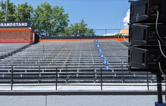
My “litmus test” for a system design is to examine how closely it meets the design goals “out of the box” before any corrective DSP is applied – specifically, in this case, front-to-back level variance. Figure 3 shows the on-axis microphone positions we used to determine the variance, and Figure 4 shows the “raw” measurement data.


Now all positions hang very closely together in the same 1 kHz to 4 kHz range, with the level variance staying well inside the +/- 3 dB design goal. This puts the overall level variance at about 5 dB front to back, which is a 7 dB improvement over the previous design. Since this consistency is accomplished solely with the geometry and splay angles, we can apply response-shaping EQ with confidence that the result will be represented well over the entire coverage area.
Although I don’t intend to enter the fray regarding the number of cabinets or length of the line required before we can refer to the deployment as a “line array,” I submit this exercise as evidence that even in small quantities, there are some substantial improvements to be made over a simple “speaker on a stick” solution in certain coverage applications. From that point, I was happy to hand the keys over to Nate to apply EQ as he saw fit.
In conclusion, I think this is a great example of how better results are possible with the proper application of better tools. Reviewing the data afterwards is a nice confirmation that the time spent seeking improvements on a design can be a good investment indeed.


