Phase Tab
When one observes a phase plot for any device, they are viewing a response that has multiple contributors. These are delay, phase shift and polarity.
One must perform some forensics to isolate these effects. The multiple paths through a mixer can be time-coherent (identical delay per path, referred to as latency), phase-coherent (identical phase response per path), or polarity-coherent (identical polarity per path). For example, two paths can have an identical phase response, but different latency. They can also have identical latency, but one path could exhibit phase shift. And lastly, the latency and phase responses can be identical, but one (or both) paths could invert the signal polarity. A phase plot cooks all of these responses together, so we must pick them apart.
The most common first step is to remove the delay by subtracting a time interval. This “latency compensation” can be done automatically by most analysis platforms.
Once the delay is removed, the phase shift and polarity remain. The polarity can usually be determined by observing whether the mid band phase response crosses through 0 degrees or +/- 180 degrees. This is typically pretty obvious for broad bandwidth, linear response devices such as mixers and amplifiers. It’s less obvious for devices that introduce significant phase shift, such as multi-way loudspeakers that use high-order analog or IIR digital crossovers.
An important distinction is that two of these contributors, delay and polarity, do not alter the shape of the waveform. Delay slides the waveform down the time axis, and polarity inverts it. In contrast, phase shift changes the wave shape by wrapping it around the time axis in a frequency-dependent manner. The audibility of this “phase distortion” has been hotly debated for decades.
The ideal phase response is a flat line. This is linear phase. It means that the device does not cause a phase shift between the various frequencies that pass through it, allowing the shape of a waveform to be preserved. A square wave played into the input would look like a square wave at the output.
One reason that the frequency response of a mixer extends beyond the 20 Hz – 20 kHz audible spectrum is to maintain a linear phase response out to these frequency extremes. All of the mixers tested would do a good job of preserving the shape of a square wave, but all would delay it by a different amount. One mixer inverts the signal polarity.
Timing Tab
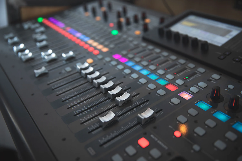
The original objective of this study was to evaluate how signals that are routed to a main bus via different paths mix together. Any timing differences can destroy the mixer’s fidelity. This a problem that plagues many digital mixers. To be fair, it is not so much a problem with the mixer as it is with how the mixer is used. For some consoles, it is a bad practice to route a given channel directly to the main bus and then also to the main bus by a different route. The latter is sometimes done as a means of adding effects, but any timing differences caused by the longer path can cause severe tonal coloration by producing a comb filter when the signals are mixed.
A similar problem can occur with digital mixers that utilize remote stageboxes. In many cases the stagebox input will have more latency than the mixer’s onboard IO. For example, if I put two microphones on a sound source, with one connected to the stagebox and the other to the mixer’s onboard input, and then mix those two signals together, the timing difference can cause a comb filter. Again, this is not so much a mixer problem as it is a user problem, but people are going to do it so we need to be aware of any ramifications.
Some mixers are compensated by design to avoid these path length differences. Others are not. We included two analog mixers in the lineup to demonstrate the absence of latency. One is the APB Dynasonics H1020. Check out the matrix to see if you can identify the other one.
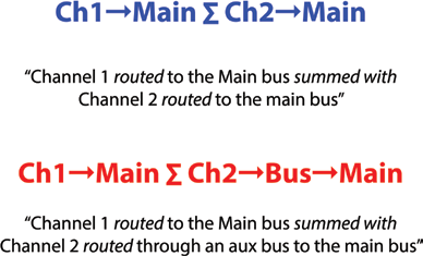
The Timing plot shows the impulse response of the mixer using the paths shown at lower right. The arrow symbol shows the path, and the summation symbol shows what is being mixed – the paths on the left and right of the symbol (Figure 4).
Any timing differences are shown in the time domain (the Timing tab). A perfect device would pass all of the signals with the same latency.
The impulse response also reveals the polarity of the mixer. A positive-going impulse means the mixer preserves the polarity of the applied signal. A negative-going impulse means that the signal is inverted by passing through the mixer (Figure 5).

Summing Tab
If a timing difference exists between two signal paths, a comb filter will be produced if the longer path signal is mixed back with the original. The Summing tab shows the frequency response magnitude of the summed signals. The effect on the mixer’s frequency response can be dramatic.
The obvious solution is to never route signals to an output bus through multiple paths. If you must, buy an analog mixer or one that has internal compensation for the path length difference.
Conclusion
On one hand this study reveals that the mixer is not likely to be the weakest link regarding sound quality for any sound system. All of the mixers flawlessly cover the audible spectrum with a dynamic range that far exceeds that of vinyl (65 dB) and in many cases that of the CD (96 dB).
On the other hand, from this study one can clearly see that all mixers are not created equal. Differences, even if subtle, always exist. There are significant challenges to producing a system response with 100 dB of dynamic range (approximately CD-quality). This requires that the gain structure of each component be fully optimized. EMI mitigation may be required on some inputs and outputs. And this doesn’t even factor in the weakest links – the microphones, loudspeakers, and room.
Audio is indeed a challenging field and the future is bright for those who can achieve good sound in the Zoom meeting era. If you would like to learn more about the concepts presented in this video, check out SynAudCon’s online training Course 100 (Principles of Audio) and Course 200 (Signal Chain Optimization).