Example 3. “Measurements on a real system”
When measuring a real PA for live or installed use, only one of the arrays should be measured.
Additionally, the microphone should be placed approximately halfway between the source and the maximum distance to be covered, assuming reasonable coherence is obtained at that location.
When we choose this centre point for phase alignment we make sure that significant phase change will not occur at any other listening position within the audience area (unless we are really close to the array), be it closer or further away from the speakers.
Make sure the floor reflection does not create poor coherence at the crossover frequencies. This is a common occurrence when using a microphone stand.
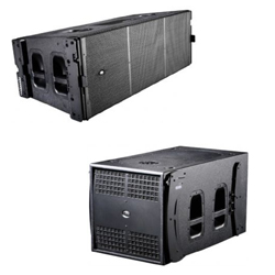
In this example we are aligning phase between a DAS Aero 50 line array and some DAS LX218A subwoofers.
The level difference between the two will make the shared frequency range narrower or wider. In our example the two systems overlap in the 45Hz to 125Hz range.

The DAS LX218A subwoofer is a self-powered system incorporating signal processing (crossover and equalization), but we will use an external processor in order to add delay for alignment to the mid-highs.
A common mistake is to filter a self-powered system at the same crossover frequencies used in the equivalent passive system, this way the slope corresponding to the external processor adds to the slope provided by the integrated crossover.
So we end up, for instance, with a sort of 48 dB/oct filter instead of a 24 dB/oct one. In our example, no filtering is used at the external processor. Only the filtering that is built into the subwoofer is used.
The DAS Aero 50 mid-high is a 3-way line array system. Each of its 3 bands has a factory specified delay time applied on an external processor.
The procedure is the same as for the previous examples:
1) Enter 20 ms as the delay time for each of the outputs in the processor (a different delay time can be used).

2) Let’s first work just with the mid-high. We’ll use the “Delay Finder” utility to add the required delay to the channel with the reference signal, i.e., to synchronize the reference signal to the measured signal. (See the user’s manual for SATlive or your analysis software for more information).
3) Measure the frequency response for the complete system before doing phase adjustments. At worst, we will see significant cancellation in the frequency range being shared by both enclosures.
4) Mute the subwoofer output, and unmute the mid-high output in the processor.
5) Measure the mid-highs and save the curve. In our example, the curve in Figure 21 is obtained.
6) Mute the mid-highs, and unmute the subwoofer output.
7) Do not use “Delay Finder” again!!! (i.e. do not synchronize the reference signal to the measured signal again).
Remember that we are comparing phase on both outputs, i.e. we are measuring the difference in time arrival between the two signals as a function of frequency.
Therefore the synchronization delay for the reference signal should not be changed on the measurement software again.
Keep in mind that we chose the mid-high box as our timing reference because it is the signal from which the best impulse response can be obtained.