In the previous two segments of this series we discussed phase and polarity, what causes phase to vary, what is meant by phase alignment, coherence curves, and we took a look at the first of three illustrative examples.
If you haven’t yet read the first two articles in the series, which are available here, I’d urge you to do so.
If you’re up to speed and ready to continue, let’s take a look at the rest of our examples
Example 2. “Scaled down measurements: the subwoofer and the mid-high box crossed-over at the same frequency”
Subwoofer crossover frequencies for the real system will be:
- HPF LR24dB/Oct, 30Hz
LPF LR24dB/Oct, 85Hz
Crossover frequencies for the real mid-high unit will be:
- HPF LR24dB/Oct, 85Hz
LPF LR24dB/Oct, 20KHz
Crossover frequencies for the scaled down subwoofer system will be:
- HPF LR24dB/Oct, 30Hz x 4.5 = 135Hz
LPF LR24dB/Oct, 85Hz x 4.5 = 382Hz
The crossover frequencies for the scaled down mid-high system will be:
- HPF LR24dB/Oct, 85Hz x 4.5 = 382Hz
LPF LR24dB/Oct, 20KHz
Place the boxes as for example 1 and follow the same procedure.
1) Enter 20 ms as the delay time for each of the outputs in the processor (a different delay time can be used).
2) Let’s first work just with the mid-high. We’ll use the “Delay Finder” utility to add the required delay to the channel with the reference signal, i.e., to synchronise the reference signal to the measured signal. (See the user’s manual for SATlive or your analysis software for more information).
3) Measure the magnitude frequency response for the complete system before doing phase adjustments. At worst, we will see significant cancellation in the frequency range being shared by both enclosures.
4) Mute the subwoofer output, and unmute the mid-high output in the processor.
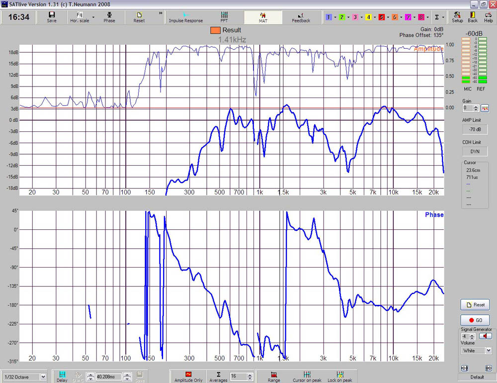
5) Measure the mid-highs and save the curve. In our example, the curve in Figure 15 is obtained.
6) Mute the mid-highs and unmute the subwoofer output.
7) Do not use “Delay Finder” again!!! (i.e. do not synchronize the reference signal to the measured signal again)
Remember that we are comparing phase on both outputs, i.e. we are measuring the difference in time arrival between the two signals as a function of frequency.
Therefore the synchronization delay for the reference signal should not be changed on the measurement software again.
Keep in mind that we chose the mid-high box as our timing reference because it is the signal from which the best impulse response can be obtained.


