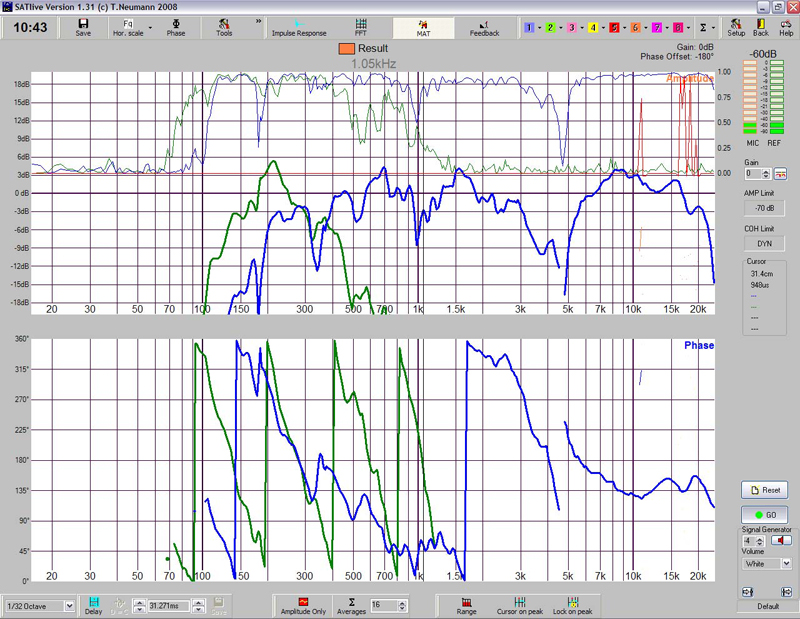
8) Measure the subwoofer and compare the phase curve with that of the mid-high box. The result can be seen in Figure 10.
9) Add or subtract delay from the subwoofer output until the two phase curves overlap around the crossover frequency. Do not forget to save the curves.
The curve with the steepest slope of the two is the one with the most delay. Therefore, it seems clear in this case that we will have to subtract delay from the green curve, i.e. the subwoofer output.
We’ll be able to do this because we initially added a delay of 20ms to the two outputs.
Remove some of the delay from the subwoofer output and the green curve will loose slope and shift upwards, and the two phase traces will overlap within a fairly wide band.

The delay on the subwoofer output ended up at 18.666ms. From 150Hz to 400Hz the two curves overlap, i.e. they are in phase within the entire band they share.
Therefore, if we compare two phase curves and we want to minimize the difference in phase between them, we need to remember the following: if a curve has a steeper slope than the other, it’s arriving late and we need to take away delay.
If a curve has a gentler slope than the other, it’s arriving early and we need to add delay.
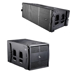
Keep in mind that, in our example, the subwoofer was physically forward with respect to the top box, so we could have mistakenly assumed it was the subwoofer that needed delaying.

Do not forget that filters have an effect on phase, and therefore we cannot predict if we need to add or remove delay until we see the measurements.
Let’s see what would have happened if we had increased the delay time to the subwoofer instead of reducing it.
In Figure 12 delay has been added to the subwoofer output until the most overlap was obtained. The subwoofer delay ended up as 22.276ms.
Phase overlaps in the 250-300 region, which is very little. Below 250Hz the blue phase trace is below the green one, whereas above 300Hz the green curve is below the blue one; i.e. there’s phase difference between them.

10) Measure the system frequency response and compare it to the initial measurement.
If phase has been correctly adjusted, subwoofers and mid-highs will sum in phase and this will be reflected on the magnitude frequency response.
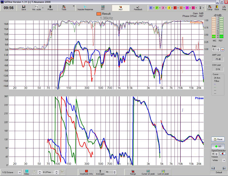
Figure 13 compares the system combination without adjustment (red trace), with 22.2766ms delay on the subwoofer (green trace) and with 18.666ms (blue trace).

It can be clearly seen that the best sum occurs for the 18.666ms subwoofer delay.
11) Take the lowest delay value and subtract it from the subwoofer and mid-high so that at least one of the outputs has a delay time of 0ms.
At this time there’s a delay of 20ms on the mid-high and 18.666ms on the subwoofer.
Since we had added 20ms just as an arbitrary amount to be able to add or subtract from that as needed, once the adjustments have been made we no longer need that excess delay: subtract the lowest delay time from the two outputs so that one of them has 0ms.
In our example the mid-high output will end up with 20ms – 18.666ms = 1.334ms. The subwoofer output will have 18.666ms – 18.666ms = 0ms.
Stay tuned for the coming articles in this series, where we’re lay out additional examples. Want to get a jump on the reading? Head on over to the DAS Audio Website where you can DAS Audio Engineering Department.
