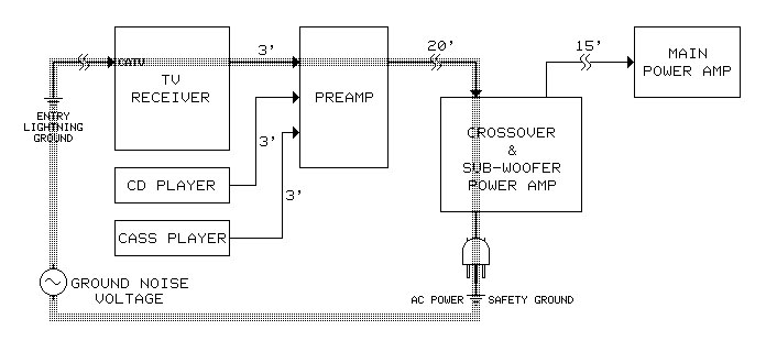
When a system contains two or more pieces of equipment that are grounded, whether via power cords or other ground connections, a “ground loop” will likely be formed. (See Figure 1, below.)
Although ground loops often involve power line safety ground connections, disabling them is both highly dangerous and illegal.
However, devices called “ground isolators” can be inserted in the signal path to break the loop safely. This approach attacks the problem at its fundamental roots, while tampering with safety ground does not. In simple language, a ground isolator is a device that transfers a signal across an electrically insulated barrier.
This is how it stops the flow of power-line currents that would otherwise generate noise as they flow through signal cables. Because an isolator is not a filter that recognizes and removes noise, it must be inserted in the signal path at the point where the noise coupling actually occurs.
On the other hand, a transformer can serve as an extremely effective ground isolator. As shown in Figure 2, it transfers signal voltage from one winding to the other without an electrical connection between them. This electrical isolation blocks the flow of ground noise current in the signal cable.
While the isolation would be total for an ideal transformer, physics imposes limitations on real-world transformers.
Two Basic Types
In practice, noise reduction depends critically on the design of the transformer. Audio transformers fall into two basic types.
The first, known as an output transformer, is by far the cheapest and easiest to build. Because its primary and secondary windings are physically interleaved, considerable capacitance is created which allows noise currents, especially at higher audio frequencies, to flow between windings. This limits its ability to stop ground noise.

The second type, known as an input transformer, is built with internal metal foil shielding between its windings. This “Faraday shield” effectively eliminates capacitive coupling and vastly improves noise rejection. A magnetic shield serves a completely different purpose and, if used, is on the outside of a transformer surrounding both the core and the windings.
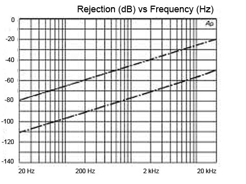
Figure 3 shows noise rejection versus frequency for a typical unbalanced interface. With no isolator, by definition, there is 0 dB of rejection in the interface, as shown in the upper plot.
The middle plot in Figure 3 shows results for a typical isolator using an output transformer. Hum at 60 Hz is cut by 70 dB, but buzz artifacts around 3 kHz are reduced by only 35 dB. The lower plot shows results for a typical isolator using an input transformer. Hum is cut by over 100 dB and buzz by over 65 dB.
The overwhelming majority of “black boxes” intended to solve ground loop problems use output transformers. One advantage of these boxes is that they can be installed anywhere along the length of a cable or can be used at patch-bays. Although boxes made with input have some 30 dB better noise rejection, they must be installed thoughtfully.
In Figure 4, we see a commercial black box. Because high-frequency response can be degraded by excessive cable capacitance at their outputs, these types of boxes must be installed near the equipment input they drive, generally through no more than 3 feet of cable.
Some commercial interface devices are “active” (i.e., powered) devices. Although these often have useful features, they invariably use differential amplifier circuits to “isolate” their unbalanced inputs.
In a future discussion of balanced interfaces, we’ll find that ordinary diff-amps do this job very poorly. Typical products in this vein often deliver only 15 dB to 30 dB of noise rejection under typical real-world conditions.
Incidentally, to eliminate noise in an unbalanced cable run, it’s not necessary to “balance” the line (using a converter at the driving end) and then “unbalance” it (using another converter at the receiving end).


