
There are few hard, fast rules in this world of music and art, but one thing is always for sure — the drummer wants it louder in the phones. The singers could be wracked with pain, tears in their eyes and still the drummer will want more volume. You could swear they’re all deaf. (Hmmm? … )
So here, to the rescue, we have a booster amplifier packing — hold on to your hats — a whopping 1.25 watts into a pair of 8-ohm stereo headphones. Coupled with a relatively efficient pair of cans, this combination could be lethal.
But seriously, the idea is to reduce the overall cue feed level to something more comfortable and then give the booster to the percussionist. (Here you go, Jack, blow your brains out.) A volume control has been provided allowing the drummer to be in complete command, though obviously anyone can use it. But it has been designed for a drummer’s use since it includes an electronic metronome which allows the drummer or other principal timekeeper to hear a steady beat along with the music. If you want everybody to hear the metronome in their phones, its output is available for feeding into the control room.
Since the electronic “click” sound is relatively neutral and resonance-free, an equalizer may be used to create a tone quality that will help to stand out in the mix. A parametric EQ would be the most useful — set for a narrow peak and give it a healthy boost. In the midrange, this will bring out a wood block or claves type sound. Lower down, near 80 or 100 Hz, a boost (use less here) will sound like a kick drum. Cut out some midrange and it will sound even better.
Play it through a good speaker and then mike that — you’ll think it’s the real thing. But there are even more uses for a metronome in the control room. For one, you can keep your 30-second spots to 30 seconds. Or, you can lay a steady beat on the master tape to hold things together if the drums won’t be added till later. In fact, a metronome can be so handy in the studio that many readers may want to build only that part. No problem. Eliminating the power amplifier will allow battery operation which further simplifies construction. Simply hook up a 9-volt battery to the timer ICs and away you go. No other changes are required, though the output level will drop by 6 dB or so.
Most mechanical metronomes have a range of from 40 to 208 beats per minute. The electronic version presented here has been designed to slightly exceed this range to take component tolerances into account. Final calibration amounts to little more than counting beats and timing with a stopwatch. Marks may be made on the panel indicating the tempo or you could go all out and have your unit professionally painted and screened.
As you might imagine, operation isn’t very complicated. In addition to the tempo adjustment, there are two volume controls — one for the music and one for the metronome. The user can set any balance desired without disturbing the main cue feed. Incidentally, the music is maintained in full stereo, while the metronome is fed equally to the two channels.
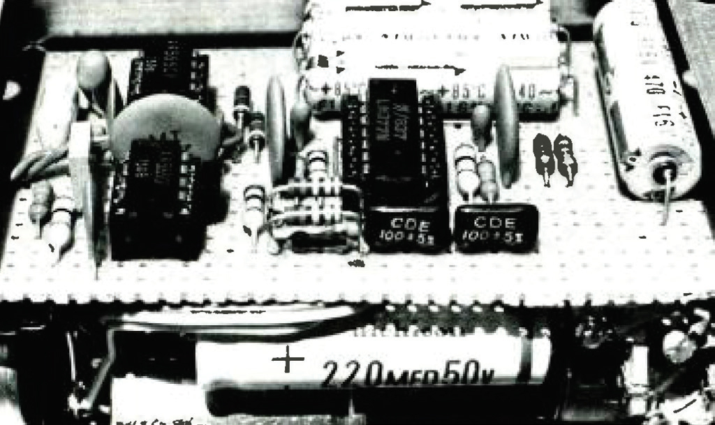
Construction
Little difficulty should be encountered, even for novice builders, as the circuit is relatively simple. Also, a printed circuit board is available from the author for a nominal cost, though some readers may prefer to use perf board. Either method should work fine, but another decision will need to be made regarding input and output connectors.
The prototype was built into a fairly small aluminum box with a 1/4-inch stereo phone plug sticking out the side allowing the whole thing to plug directly into the cue jack on the wall. This may not be practical if a larger enclosure is used and you may be better off with a two or three foot wire coming out the side for the input. This also allows you to use any connector type you want, or even to change later on.
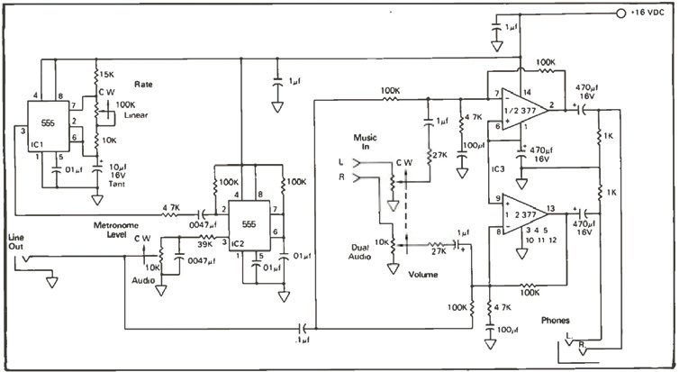
About The Circuit
For the metronome, two 555 timer ICs are used — one to set the tempo and the other to generate the click sound. The 555 was chosen for several reasons. The accuracy of the timing is independent of the power supply voltage so the markings, once established, will not change.
This becomes especially important when powering the device from batteries since the timing must not vary as the batteries age. Variations in temperature won’t have much affect either on this little guy. The 555 is very common, inexpensive, and available nearly anywhere electronic parts are sold. The 377 power amp IC is also pretty common and has similar tolerance to variations in operating conditions. But to stay with the timing circuit for a moment, we should quickly go over some of the other components.
No matter how stable the IC may be, unless the remaining parts are of a similar high quality, full advantage may not be had. The 10 mf capacitor should be tantalum if possible and the 10K and 15K resistors should be carbon film (or better, metal film if you can find them). A wirewound potentiometer is also preferable, but this may be even harder to track down. If you can’t locate these special parts, or if you’re too lazy to try, don’t let that stop you from building this.
In fact, I didn’t bother with the wirewound pot either and mine works fine. Still, there is some satisfaction to be had from knowing it’s the best that it can be. No other parts are critical at all, though don’t buy the cheapest stuff you can find either.
Regarding hard to find parts, one real winner is the dual taper potentiometer. One good place to order this and other hard to find parts is Mouser Electronics, 11511 Woodside Avenue, Lakeside, California 92040. While even they may not have in stock dual audios, you can get a dual linear in a higher value, which in many cases can approximate the audio curve.
Incidentally, Mouser is the only source that I know of for audio inductors and radio coils. (Stay tuned for an article on a barely legal AM transmitter you can use to broadcast your mixes to a car radio.) But back to tapers, for those of you who don’t understand the different kinds, a brief explanation is in order.
A linear tapered pot is used to “divide” a voltage or an audio signal linearly. That is, when the control is turned half way up, the output voltage is half that of the input. A quarter way up gives a quarter of the signal out. While this makes sense for many applications, it is less useful as a volume control since the ear doesn’t perceive loudness in a linear fashion.
With an audio tapered pot (sometimes called logarithmic), when the control is set half way up, only one tenth of the total output has been reached, allowing another 20 dB of range till full open. (Remember, increasing by 20 dB corresponds to multiplying the voltage by 10.) Many guitar amps are intentionally made with a linear pot for a volume control to give the impression of a large power reserve. (Gee, it’s really loud and it’s only on two and a half!) Unfortunately, most of the useful range has been crammed into the first quarter of a turn, making adjustment more difficult than it needs to be.
In the case of our metronome/booster, a dual 100K linear pot may be used instead of the dual 10K audio pot specified and the music will be about 12 dB down from maximum with the control set in the middle. While this may be less than optimum, it does help spread out the range some.
Performance
For the amplifier, you can expect the worst case THD to be less than .1 percent when using 8-ohm phones, and even less with higher impedance models. Frequency response is equally impressive, being within 1 dB from 20 Hz to well beyond 100 kHz. Gain of the audio program will be just over 10 dB with the volume control all the way up. If you need even more, you can reduce the 27K resistors to 10K which will allow up to 20 dB of increase.
Regarding the metronome, there isn’t much to spec except possibly for stability of the tempo. The biggest factor here will be variations in temperature, since all electronic components are affected this way. In fact, this is the main reason film resistors and tantalum caps were mentioned as being preferable. The 555 IC varies less than .01 percent for each degree (F) of change in the ambient room temperature.
PARTS LIST
2 – 555 TIMER ICS
1 – 377 AUDIO POWER AMP IC
1 – BRIDGE RECTIFIER, 50 VOLT/1 AMP
2 – 1K 1/4 WATT 5% RESISTORS
3 – 4.7K 1/4 WATT 5% RESISTORS
1 – 10K 1/4 WATT 5% RESISTOR
1 – 15K 1/4 WATT 5% RESISTOR
2 – 27K 1/4 WATT 5% RESISTORS
1 – 39K 1I/4 WATT 5% RESISTOR
6 – 100K 1/4 WATT 5% RESISTORS
1 – 10K POTENTIOMETER, AUDIO TAPER
1 – DUAL 10K POT, AUDIO TAPER OR DUAL 100K POT, LINEAR TAPER (SEE TEXT)
1 – 100K POT, LINEAR TAPER
2 – 100 PF 10% DISC CAPACITORS
2 – .0047 MF 10% DISC CAPACITORS
3 – .01 MF 10% DISC CAPACITORS
2 – .1 MF 10% DISC CAPACITORS
2 – 1 MF/16 V ELECTROLYTIC CAPACITORS
1 – 10 MF/16 V TANTALUM CAPACITOR
3 – 470 MF/16 V ELECTROLYTIC CAPACITORS
1 – 1,000 MF/25 V ELECTROLYTIC CAPACITOR
1 – ON/OFF SWITCH
1 – 1/8 AMP SLO-BLO FUSE IN HOLDER
1 – LINE CORD AND GROMMET
1 – POWER TRANSFORMER, 12.6 V/400 MA SUITABLE ENCLOSURE, HARDWARE, INPUT AND OUTPUT CONNECTORS
Note: A drilled and plated PC board for the metronome/amplifier is available for $9.50 post paid from The Recording Center, Inc., 25 Van Zant, East Norwalk, CT 06855.