
Previously (Mind The Gap) we looked at my preliminary findings about the (possibly) beneficial effect of introducing gaps between adjacent enclosures in cardioid stacks and arrays.
Here, I’d like to delve into that further.
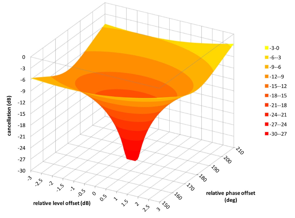
The conditions for perfect cancellation are very stringent. I’ve come to call this state the “center of tranquility at the eye of the storm.” Notice how the chart in Figure 1 resembles a tornado.
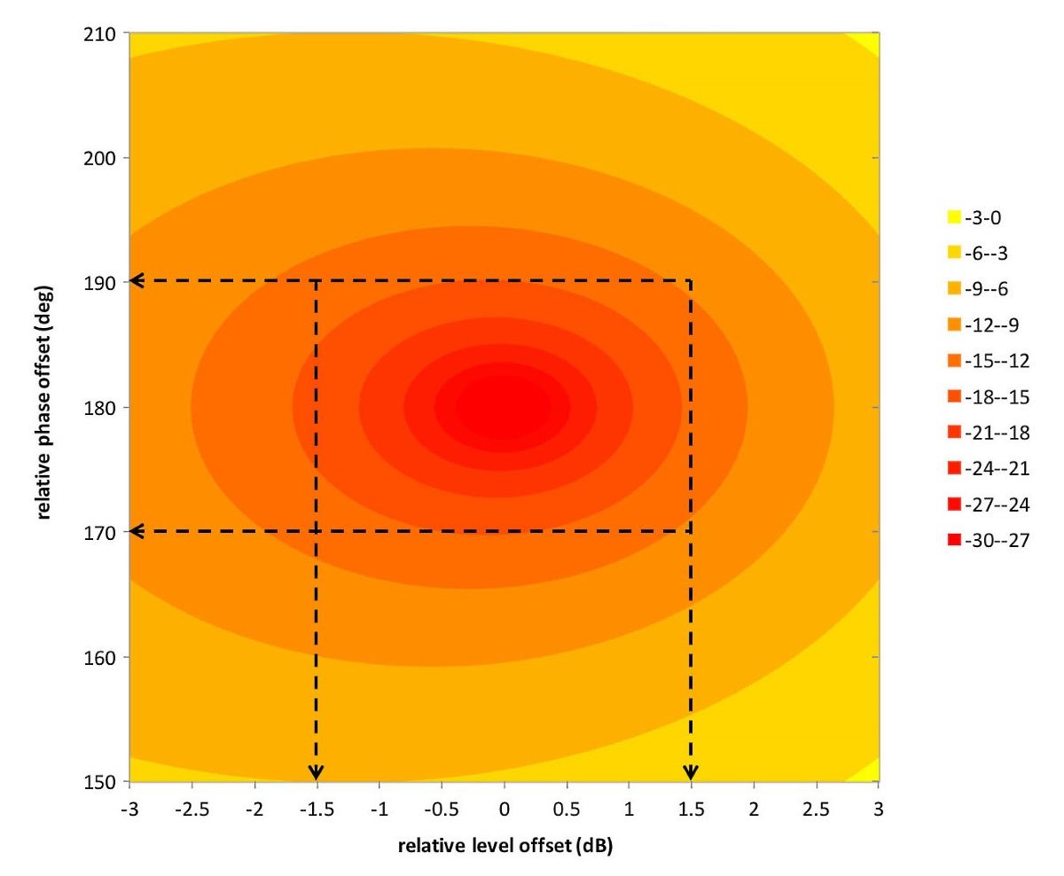
A two-dimensional rendering of this chart (Figure 2) shows that relative level offsets should remain within ±1.5 dB and relative phase offsets within ±10 degrees in order to achieve 15 dB cancellation or more.
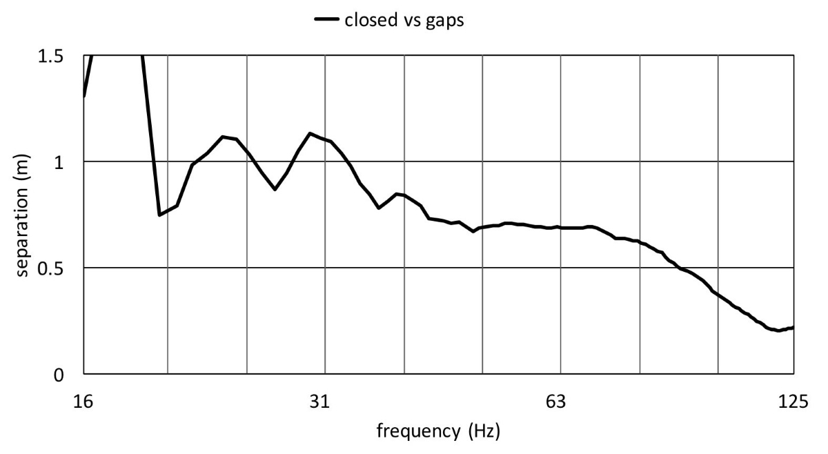
Let’s look at an example of the measurements I conducted on the grounds of a former air force base. Figure 3 shows the relative back-to-front (rear-facing vs. front-facing subwoofers) level at a distance of 105 feet (32 meters) behind a horizontal front-back-front-back-front (FBFBF) array in portrait orientation.
Notice the increasing level difference towards higher subwoofer frequencies when the array is closed (without gaps). This is caused by diffraction that increases with the overall baffle size of the entire array. Remaining within the ±1.5 dB corridor is quite challenging.
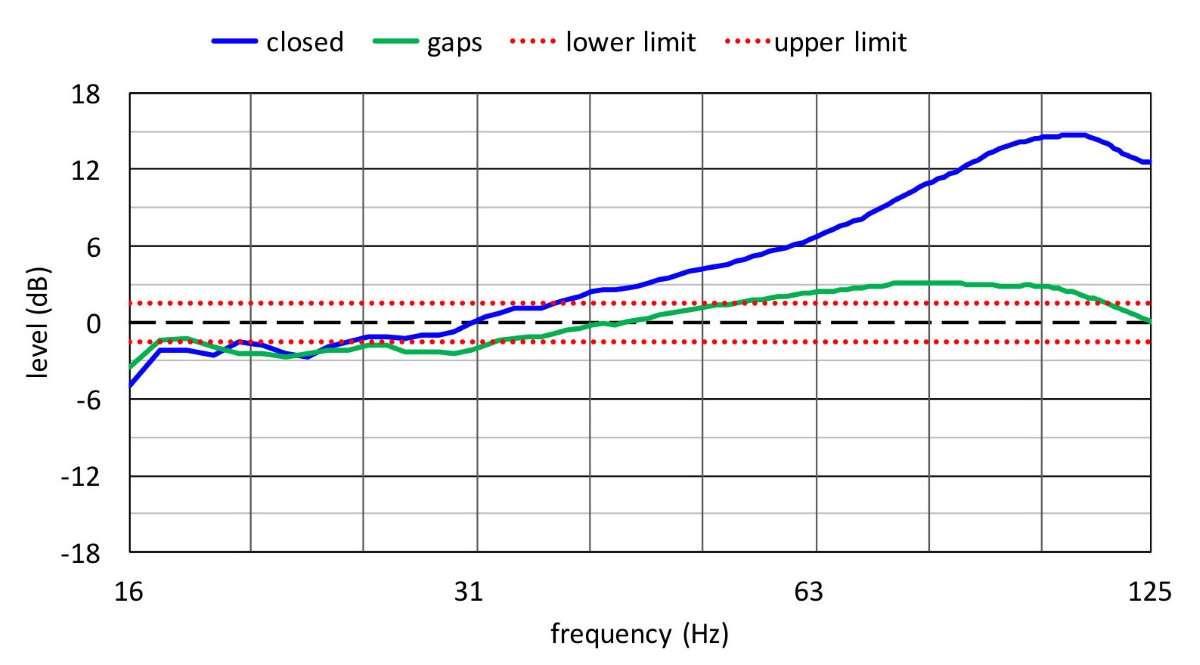
Evidently, this could easily be remedied with either electronic level adjustments and/or equalization. However, this is a practice I refrain from out of concern for “pattern implosion” when limiters engage at different stages due to these electronic adjustments. Changing the ratio of back-to-front-facing subwoofers, in my opinion, is a more elegant solution.

With gaps, the diffractive effect is less pronounced (due to the breakup of the combined baffle) and relative level differences remain more predictable unless one has access to something such as Boundary Element Method (BEM) modeling that exhibits these phenomena.
Phased Out
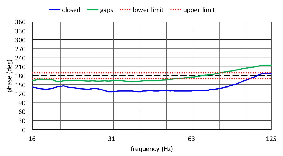
Figure 4 shows the relative phase offsets. This observation alone made the entire measurement process worthwhile for me. With or without gaps, using the same delay time mandatory for gradient (CSA) setups has a profound effect on the relative phase offset, bordering the point that neither cancellation nor summation will occur (120-degree phase offset).
Interestingly enough, group delay (phase slopes) remains virtually identical and yet we observe a “broadband” constant phase offset. It’s something that, to my knowledge, can’t be corrected with simple (pure) electronic delay. Staying at 180 degrees (±10 degrees) is again very challenging.
In the past, I would blame this on arrival times as well as the “wraparound” time, i.e., the time it takes for the sound to warp around its own enclosure or array (think obstacles). But the geometry of this setup does not support this.
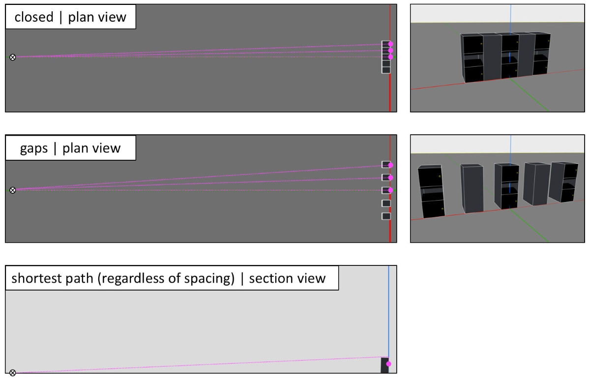
Figure 5 shows the dimensions we’re dealing with. At a distance of 105 feet, the spacing effect is negligible for path lengths — certainly not to the degree we’re measuring.
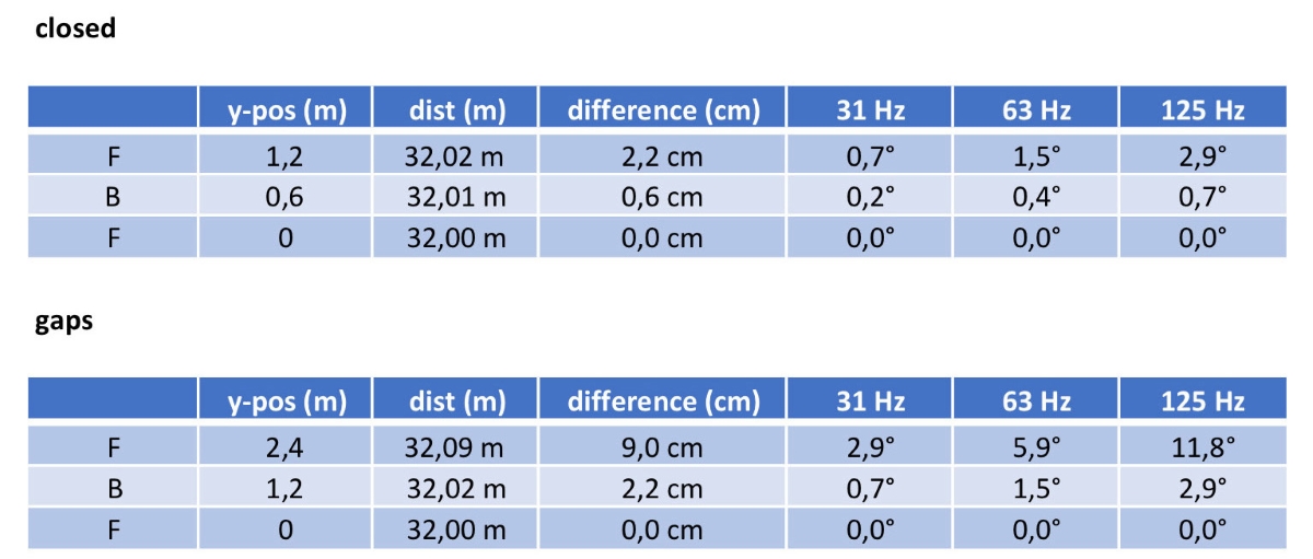
The table in Figure 6 shows that we’re literally talking centimeters, resulting in approximately 10 degrees of additional phase delay at most for the highest subwoofer frequencies only.
In addition, in either case, the spacing does very little to the shortest possible path anyway (Figure 5, bottom left). If anything, the gaps only make it shorter. A different way of thinking is required.