
In part 1 of this series (here), I offered an overview of networking concepts and terminology and discussed some of the possibilities when integrating networking technologies into audio, video, and lighting (AVL) systems. This time, I’ll go into some of the more technical concepts.
When I first started working with networks in AV systems, I came across many different technologies that worked in different ways. It was hard for me to understand why some things needed IP addresses but not others, why I could connect some things through network switches but only some would work if you connected the devices directly to each other. Then I learned some conceptual models that help explain how networks operate.
You may have heard of network technologies that operate in various “layers” such as, “Dante is a Layer 3 protocol” or “Aviom is Layer 1.” While it’s common vernacular for my work, this is likely new for many people. There are two main models used for explaining how networks operate: the TCP/IP model and the OSI model. In AVL networking, the OSI model is most common so that’s what I’ll focus on here.
What Is It?
The OSI (Open Systems Interconnect) is a conceptual model that has been around since the late 1970s and provides a framework that will help you understand how different network technologies operate and relate to each other. It’s a hierarchical series of layers that represent how different data communicates and is transferred.
Each layer is dependent on the layer below and serves the layer above. The original model shows 7 layers, but over the years people have jokingly added some fun layers on top such as Layer 8: the individual; Layer 9: the organization; and Layer 10: government/legal.
Some have also added the religious layer in there to reference all of our church-related situations. For example, if a musician brings some weird gadget and now you have to figure out how to make it work with your equipment, that’s probably Layer 8.
For our purposes, we need to focus on Layers 1, 2 and 3, which are known as the Media Layers. One of the benefits of understanding this model is that it helps in determining where different AVL protocols operate and how they interact, as well as their compatibility with different networking standards. Each protocol is a different standardized method of transferring information, whether that’s live audio on a digital snake, an iPad controlling a console, or a computer loading a video from the internet (Figure 1).
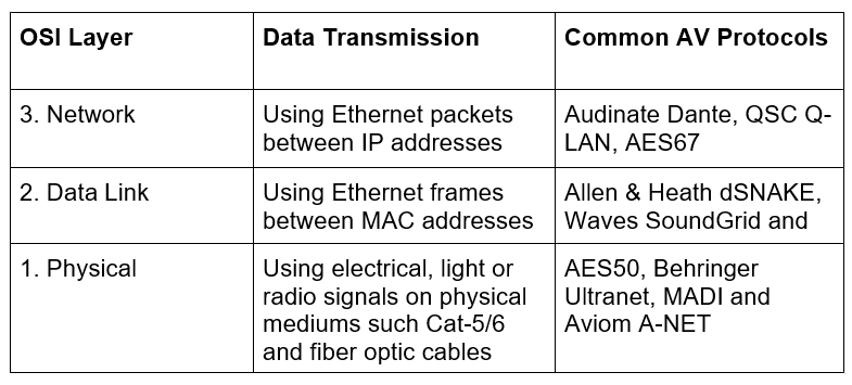
Layer 1: Physical
As the name implies, this layer represents the physical cabling, connectors, and other mediums through which the data is transmitted. This data is typically binary ones and zeros of electrical signals. Many of these protocols operate in different layers within their own systems but they aren’t compatible with the higher layers in the OSI model.
Some common Layer 1 protocols that you may have seen on your equipment are AES50, Behringer Ultranet, MADI, and Aviom A-Net. Because they operate at Layer 1, they use only the cabling standards such as Cat-5/6 and can’t traverse through Layer 2 equipment such as network switches.
One of the most common problems I’ve seen in working with churches is trying to connect Layer 1 digital snakes to their consoles (for example, a Behringer X32 console to an S16 stage box) using a network switch – consulting the OSI model and we see why this doesn’t work. A switch operates at Layer 2 but remember that Layer 1 protocols only share the cabling standards. This confusion is the result of the same types of cables and connectors being used for a lot of different things. Just because the cable or connector is the same does not mean it’s compatible.
This is similar to how microphones and DMX lighting equipment both use 3-pin XLR connectors but can’t communicate with each other. Layer 1 systems are typically pretty easy to design and install. Run the prescribed cabling, terminate correctly, and plug them in.
Layer 2: Data Links
These devices connect physically using Layer 1 infrastructure but communicate with each other via a hardware address (Usually called MAC address, which is short for Media Access Control) using ethernet frames. Ethernet frames are strings of binary data that contain, among some other things, information such as the source and destination MAC address and a payload of data that’s being transferred.
Some common Layer 2 protocols are Allen & Heath dSNAKE, Waves SoundGrid and CobraNet, and they can traverse network switches, which are able to see the source and destination MAC address in the ethernet frame and send that data to the correct device.
Most Layer 2 systems are plug-and-play as far as their network configurations go, although you have to set up audio routing and patching on the hardware. These protocols aren’t concerned about the physical medium being used (Cat-5/6, fiber optic, WiFi, etc.) unless that medium introduces things like latency or other factors that the protocol can’t tolerate.
For example, there could have a network switch at the stage and another at front of house connected via fiber, and and a console plugged into the front of house switch, and you’d be good to go because you’ve maintained a reliable Layer 2 link between both devices.
What must be maintained, though, is that the path meets the specific specs for dSNAKE (or whatever the Layer 2 system might be.) For instance, even though WiFi is a combination of Layer 1 (radio waves) and Layer 2 (network protocols), it won’t work for dSNAKE because it introduces latency into the network that the dSNAKE protocol will not tolerate.