A short time ago I was very fortunate to gain access to a former air force base featuring ample real estate with a solid underground. It was an ideal environment for subwoofer measurements where I got to measure all typical inverted stack cardioid configurations.
While I’m still in the middle of processing all data, I would like to share one preliminary but potentially interesting observation.
About The Measurements
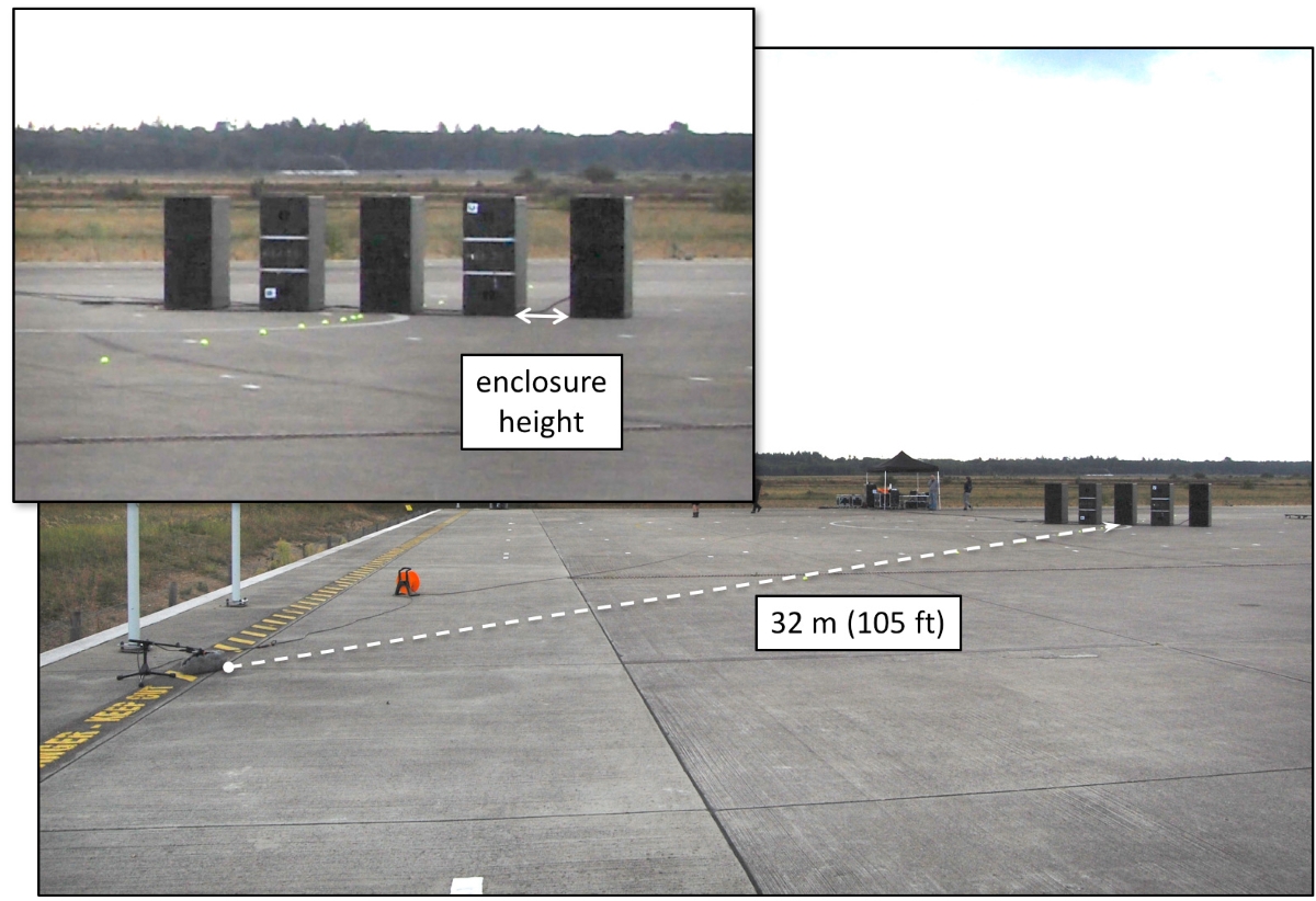
All measurements were conducted in half space at a distance of 105 feet (32 meters) using matched microphones with correction curves shock-mounted inside modular windshields (bottom left corner of Figure 2), along with windjammers that suppress wind noise by 30 dB.
The basket of a windshield is relatively small in comparison to the wavelengths of interest and will act like a pressure chamber free from standing waves due to its unique shape. With shield and jammer in place, I measured 0.5 dB of linear attenuation in the frequency range of interest.
The signal coming out of the microphones was monitored at all times using headphones. Temperature throughout the day was about 65 degrees Fahrenheit (18 degrees Celsius, ± 1 degree). All measurements exhibited 97 percent coherence or more in the decade between 20 Hz and 200 Hz, which translates to approximately 30 dB SNR (signal-to-noise ratio).
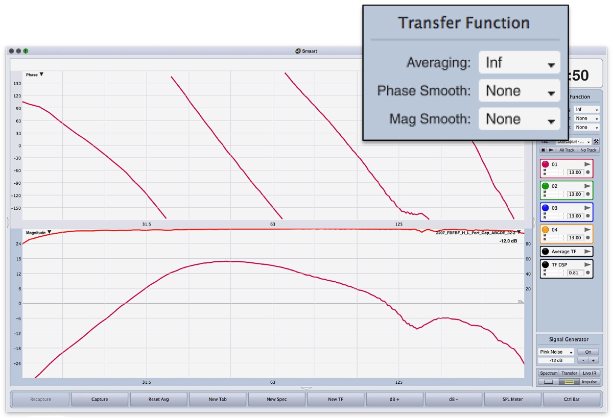
The quality of the data without any smoothing is amazing, as can be seen by looking at one of several hundred traces in Figure 1.
Building A Wall
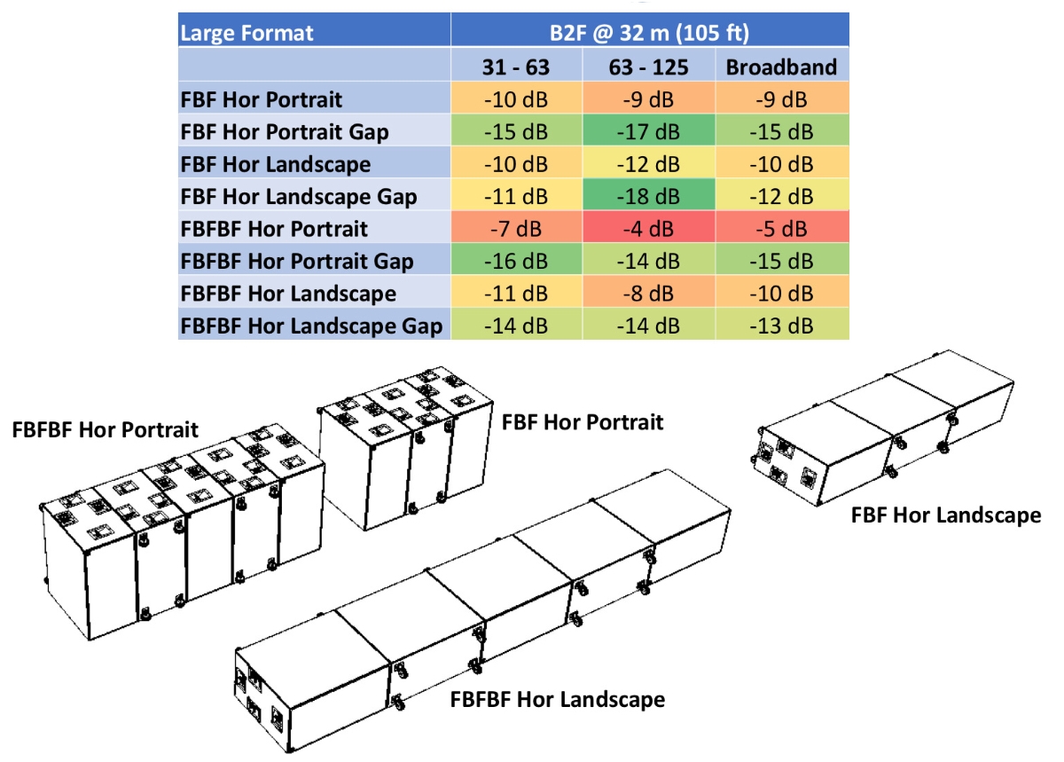
Stacking subwoofers either vertically or horizontally effectively builds a wall — a wall that’s relatively big, even for wavelengths the size of shipping containers at 30 Hz to Mini Coopers at 125 Hz. On a hunch, I decided to introduce one-enclosure-height (wheel board) gaps between adjacent subwoofers to observe the effect (Figure 2). The outcome was quite exciting.
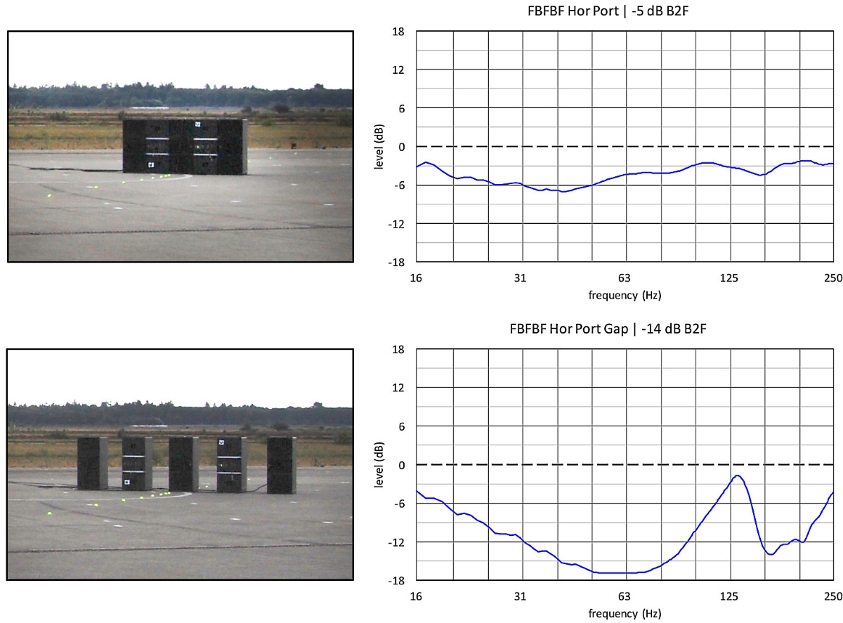
Figure 3 shows the normalized relative back-to-front level difference for a horizontal portrait orientated front-back-front-back-front (FBFBF) stack without and with gaps. The latter’s performance, on average, is three times better!
This increased performance is also observed in other arrangements shown in Figure 4. Without exception, the rejection is better with gaps.
Size Of The Gaps
The trade-off of the gaps is increased lobing, particularly at higher frequencies, due to the increase in physical displacement between the sources. The challenge becomes to determine the minimum required gap size for improved rejection without a noticeable increase in lobing.
I shared my preliminary findings with some colleagues, and they began experimenting with air gaps between adjacent enclosures as little as the size of a fist and report improved rejection. My own observations also confirm this.
I intend to further experiment with simple spacers between vertically stacked subwoofers and it might very well turn out that even the casters underneath a dolly or wheel board could prove advantageous. I’ll report on these findings in a future issue.
The author would like to sincerely thank the following people and companies for their support on this project:
— Heijmans and The National Military Museum for providing access to the premises at the former air force base (located in Soesterberg, The Netherlands).
— Sound & Light Import, which sponsored (including transportation) the loudspeakers, amplification and processing.
Audio Electronics Mattijsen, which sponsored the Rycote windshields.
— Timo Beckman, Tom de Haas, Dico ter Maten, Vince van Seggelen and Lieven Verzele for the heavy lifting and good company; additional thanks to Dico for driving the truck and making sure that all equipment was running and working as advertised.