Let’s take a poll: how many of you use some type of map to find the most efficient route to get where you’re going?
Wow, a couple of folks actually raised a hand! It may seem odd, but one of the best ways to understand how to operate a mixing console is to learn its signal flow.
Figure out a simple road map that illustrates how the signal gets from the input to various outputs.
Without this understanding, then the likely approach is your one of, “Well, if I twiddle these three knobs just so, push this fader up to here, and never ever let the master fader go past this indelibly engraved red mark that someone has carved into the face of the console, then maybe it’ll work today!”
There really is a better way, and it’s the concept of signal flow logic. Let’s get down to work.
Figure 1, below shows the input strip from a hypothetical but typical console. We’ll talk about each of those controls as we make our way through the signal flow.
On the surface, one might think that the sound flows through each control in sequence from top to bottom. Actually, manufacturers have arranged the controls in a way that they think will be the most efficient way to operate the console.
For example, controls that you would for the most part “set and forget” are placed at the top of the input strip, well out of your reach, such as, say, the microphone trim.
Controls for immediate and frequent access are placed right at the user’s fingertips, like the channel faders.
As we move on to the signal flow diagram later, it’s a good idea refer back to Figure 1 from time to time. It helps tie the signal flow into the related controls.
Applied To All
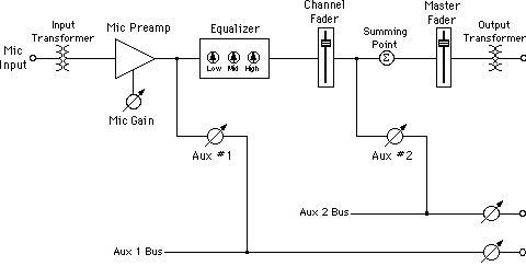
The signal flow diagram (Figure 2, below) is again from a hypothetical console. This arrangement of the controls is fairly common, and once one understands this concept, it can be applied to all consoles.
The diagram reads from left to right, top to bottom. So we start at the upper left corner at the mic input – a very good thing to have on a console! The first component that the signal sees is the input transformer.
Now, the reality is that on most consoles we work with today, especially on lower cost consoles, the input transformer is actually replaced by a less expensive electronic circuit that accomplishes much the same task.
The purpose of this input stage on each channel is to receive the balanced signal from the microphone and to cancel any extraneous noises.
The strength of that mic signal is quite low, and needs to be brought up significantly to operate with a quiet signal-to-noise ratio throughout the rest of the console and beyond. That gain increase is accomplished with the mic preamp.
Note that there is a related control called the mic trim (or mic gain). This is a gain adjustment for the mic preamp that allows you to adjust for differing signal strengths coming into each channel.
If there isn’t a control labeled mic gain, it simply means that the manufacturer has chosen to keep the price of the console down by replacing that variable resistor (called a potentiometer) with a fixed resistor.


