
In virtually all modern loudspeaker systems, the enclosure contains some or all of the driver elements that comprise the system, and it separates the rear radiation of one or more cone-type drivers from their front radiation. It may also limit the rear radiation of horns and compression drivers to avoid acoustical energy returning back towards the stage.
Why separate front cone radiation from rear radiation? When a cone driver moves forward it provides positive pressure to the atmosphere, exhibiting excursion. When it moves rearward it provides negative pressure, or recursion. It does this a lot – like 1,000 times per second for a 1 kHz wavelength. If the front and rear radiated energies are not separated from each other, each will cancel the other’s output because they are 180 degrees out of phase.
There are several ways to keep cancellations from happening. The simplest is a flat baffle, an approach dating back to the early 1900s. The first baffles were nothing more than a flat surface for mounting the cone driver, its purpose being to isolate front radiation from rear radiation. The larger the baffle, the lower the frequency range the cone driver could reproduce (within its other limits, of course).
As frequency decreases, wavelengths become longer. The baffle, if it’s large enough, separates even LF front radiation that is positive from rear radiation that is negative, thus stopping front-to-rear acoustical cancellations.
As time went on, it became clear that 18- x 18-foot baffles weren’t very practical, except perhaps in fixed cinema installations. Loudspeaker designers instead came up with the idea of an infinite baffle, which is little more than a sealed box. It works.
I remember the first time I heard the infinite baffles in a friend’s Acoustic Research AR-3 loudspeakers. (I was about 14 at the time, and the record playing was Jimi Hendrix.) Since then, I’ve spent my life involved with music and sound.
As rock ‘n’ roll displaced vocal groups and big band music in the 1960s, more output was sought from loudspeakers. The bass reflex enclosure helped to fulfill the new demands for power, clarity, and extended bass.
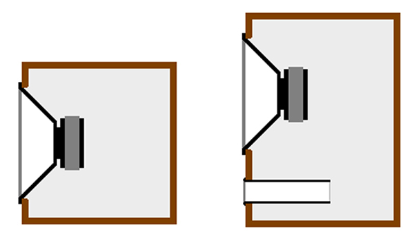
A bass reflex enclosure uses a port that captures the rear energy of the cone driver and sends it outwards by means of a relatively small, and often ducted, vent arrangement. This is not particularly intuitive (how are those long wavelengths getting through that small port?) so worry not if you can’t quite grasp it. It requires complex pressure dynamic equations to properly explain.
By Another Other Name
Bass porting (or venting as it’s often called) can be used to increase LF output, though the output from the port is not in phase with the output of the pistonic pressure from the cone.
In real life this doesn’t matter much, though you would think it should. An “optimally vented bass reflex enclosure,” a term used for years to describe LF loudspeakers in marketing brochures, can sound very good.
But if you measure its phase response, it will show a complete inversion in the frequency range where the port energy takes over from the directly radiated cone energy. Fortunately, in this same frequency range, the cone driver is moving minimally and most of the sonic energy is output through the port.
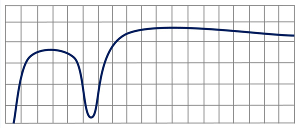
In fact, the way to measure the port tuning center frequency, called Fb in Thiele-Small terminology (the resonance frequency of driver and box combined), is to put a measurement mic at the apex of the cone and look at the response on a high-resolution spectrum analyzer.
A pronounced dip in the spectral response will be apparent. The center frequency of the dip is the box tuning frequency, and the depth of the dip roughly indicates the construction merits of the box. Even a small air leak will decrease the depth of the dip, which should be as deep as possible for maximum energy transfer to the port. An irregular shape indicates parasitic resonances such as vibrating panels.
A heavily braced, rigid enclosure will produce a smoother, better looking curve than a poorly built cabinet (see the chart directly below). In general, loudspeaker enclosures should always be as solid and inert as possible. Energy that’s absorbed by vibrating cabinet panels is wasted energy that’s not getting out front.
An alternate use of bass reflex porting is to limit excursion in a cone driver at a frequency where it might otherwise bottom out from over-excursion. In this case the port is used more for excursion control than to add output. And that leads to horn loading, which is often coupled with bass reflex enclosures in the LF range.
The Acoustical Horn
Starting with cinema loudspeakers, designers such as James B. Lansing built LF horn flares made of formed wood to increase the output of their systems. In those early days, 25-watt amplifiers were about all that were available, so loudspeaker efficiency was an extremely important issue.
Horns were also used in the upper frequencies, usually cast in malleable metal. A well-known example is the venerable Altec Lansing 511B multi-cellular horn.
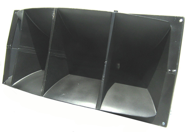
Later, fiberglass layups became the material of choice for most manufacturers (but not all). Some HF horns were constructed from machined wood, a wonderful material actually, turned on a lathe. On the flip side, other horn materials used today include plastic moldings, sometimes vacuum formed if the draft is short enough, which is a very inexpensive process compared to injection molding but only usable with thin materials.