It’s Getting Hot In Here
But there’s a problem – if you use an ohmmeter on a 60-watt light bulb, you’ll get a value for less than the expected 240 ohms. We’re missing two critical puzzle pieces.
The first is that incandescent bulbs get hot. Very hot. In fact, over 90 percent of their power is dissipated as heat, not light. What matters to us is that resistance increases with temperature. This is why the giant superconducting magnets in particle colliders are cooled with liquid helium – to keep the resistance as low as possible.
It’s also why the response of a sound system changes as it plays louder. Warm voice coils have higher resistance, and pass less current from the amplifier. This is part of the reason we have system limiters – a loudspeaker can only convert (“transduce”) so much power into sound.
Past a point, it doesn’t get louder, it gets hotter. The heated coils in the loudspeakers lose efficiency and headroom, an effect called power compression. In the extreme, this heat buildup can be the kiss of death to a system – there’s a reason we refer to failed components as “burned out.”
It takes a pretty robust rig to remain linear all the way to its limits, fighting the changing resistance as the program materials heats the voice coils, but the last few years have seen more attention paid to this issue by manufacturers. For example, this is the issue that Meyer Sound is tackling with its LEO family of loudspeakers.
So that’s one piece of the puzzle: a cold light bulb will show a lower resistance than a bulb heated to operating temperature.
AC/DC
The other reason that the light bulb doesn’t meter the resistance predicted by Ohm’s Law is that the it’s an AC device. Here’s where we need to make the distinction between resistance and impedance: “resistance” is the total opposition to current flow in a DC circuit, such as a flashlight.
However, with AC, there’s more to it. AC circuits will exhibit the same DC resistance, but there is additional opposition to current flow created by circuit components such as capacitors and inductors.
This additional opposition is due to the way these components react to the alternating current, and is called reactance (X). The AC circuits opposition to current flow consists of both resistance and reactance, so now we need a new term to describe the total opposition.
All things considered, how much does the circuit impede current flow? This is its impedance, represented by a “Z.” (Also keep in mind AC resistance, which is a frequency at which the voltage and current are in-phase (phase angle = 0), such as the resonant frequency of a loudspeaker.)
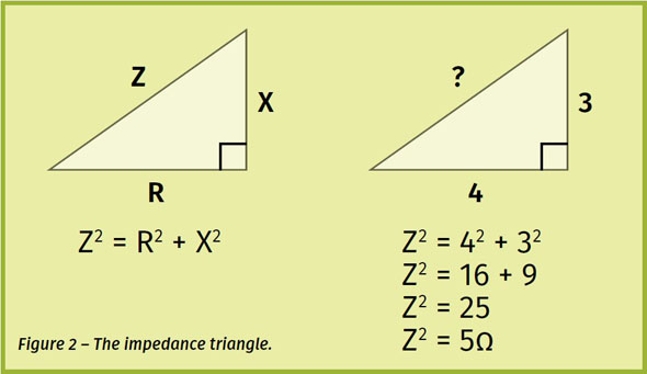
As with resistance, reactance is also measured in ohms, but we can’t simply sum the two. A circuit having 4 ohms of resistance and 3 ohms of reactance does not have an impedance of 7 ohms. Conceptually, resistance and reactance are considered as two sides of a right triangle, with a 90-degree angle between them.
The impedance is represented by the length of the hypotenuse, so we can use the Pythagorean Theorem (c2 = a2 + b2) to find it. You can see that 4 ohms of resistance (R = 4 ohms) and 3 ohms of reactance (X = 3 ohms) produce an impedance of Z = 5 ohms (Figure 2).
There are two types of reactance: capacitors cause capacitance, and inductors cause inductance. These act opposite each other, meaning they subtract, not add. If a circuit exhibits 8 ohms of inductive reactance (XL) and 6 ohms of capacitive reactance (XC) then the total reactance is 8 – 6 = 2 ohms, which is the value we would use in the impedance triangle. This is like walking 8 meters in one direction, then turning around and walking 6 meters back – you’re only 2 meters from where you started. Since the light bulb’s filament is inductive, this accounts for the rest of the discrepancy.