Because minimum-phase EQ generally doesn’t affect the all-pass behavior, we can use FIR filtering to move the phase of the loudspeaker to where we want it. Arbitrary phase manipulation has many applications, including;
- Phase linearizing a loudspeaker. (Despite the apparent improvement in the loudspeaker impulse response, there’s some debate as to whether this gives a perceptual improvement in loudspeaker performance.)
- Matching the phase (and magnitude) of loudspeakers within product lines, and across different models in projects so that they’re easier to tune in clusters and to array together.
- Manipulating individual loudspeakers in array processing (for audience overage optimization) and in beam steering.
- Crossover optimization to improve frequency response consistency within the coverage angle of a multi-way loudspeaker.
More Detailed Equalization (& Easier Filter Creation)
Using a loudspeaker measurement, we can create a frequency response (magnitude and phase) that will push the loudspeaker towards a desired target response. Because of the inherent relationship between the impulse response and frequency response, FIR filter coefficients can be generated from a desired frequency response fairly easily using DFT (or FFT) methods. The target response can be anything including:
- Pink noise flat;
- Pink noise flat with slight HF roll-off (such as Cinema X-Curve);
- Flat (linear) phase;
- The magnitude and phase response of another loudspeaker;
- The magnitude and phase response required from array processing calculations.
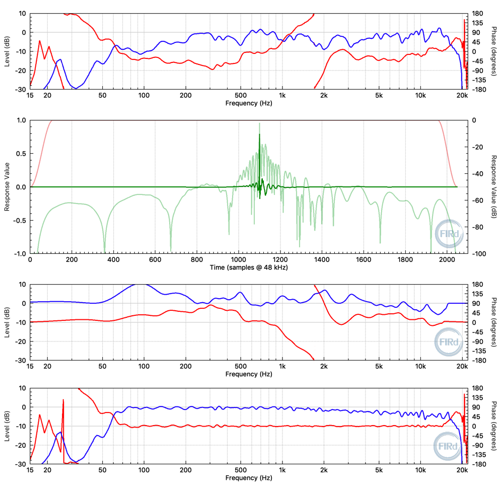
Figure 6 offers four plots showing an on-axis measurement of a commercial 12-inch, 2-way loudspeaker and a 2048 tap FIR filter created to push the cabinet’s response to have a relatively flat magnitude response (with a slight HF roll-off) and flat phase in the pass-band.
A note about designing EQ from measurements and measurement averaging:
Attempting to EQ fine structure and ripples in loudspeaker responses can be problematic. A loudspeaker’s response varies with microphone and loudspeaker position, with level and temperature, and even over time. Fine EQ designed from a single measurement might result in the loudspeaker sounding better for the conditions and position of the measurement, but is likely to make the loudspeaker sound worse at other positions and at other levels, etc. Great care must be taken to ensure the measurement is relevant and useful under all the conditions the loudspeaker will be used in – for example, within the whole of the intended coverage area. Averaging measurements from multiple locations is one way to create a measurement that can be used as a starting point for effective, fine EQ.
FIR Filtering For Subwoofers?
Figure 7 shows an example of using a FIR filter to both EQ a subwoofer and unwrap the low-frequency phase (from the cabinet and the high-pass IIR used to protect against over-displacement).
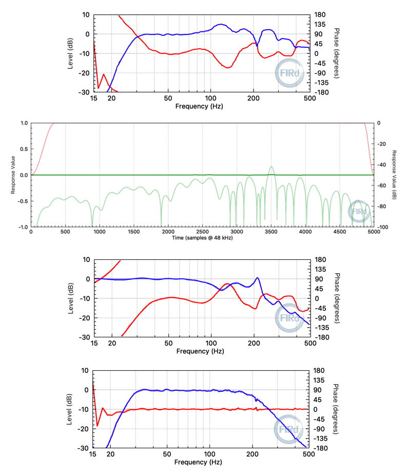
Filtering at very low frequencies requires very long filters; here 5000 taps at 48 kHz with an IR peak delay of 3500 taps, or 72.9 ms. (This is simply an example of what a FIR filter can do and it’s yet to be tested whether the reduction in low-frequency group delay improves the perceived sub impact. With such a large delay, it’s probably not useful for live applications but may be useful in cinema and home theatre applications.)
Designing & Loading Custom FIR Filters
The growing awareness of the benefits and flexibility of FIR filtering in audio, combined with the ever-increasing performance-versus-cost of microprocessors and DSPs, has resulted in increasing numbers of audio products with user-accessible FIR filtering blocks. These products enable loudspeaker designers, installers, system operators and DIY’ers to load custom FIR filters.
Software tools like FIR Designer from my company, Eclipse Audio, enable the design and simulation of FIR based EQ and mixed IIR+FIR presets/tunings for loudspeakers and systems, from loudspeaker or system measurements. Comprehensive measurement averaging functionality for spatial and level averaging is also included.