The filters in the two previous examples calculated the sum of a scaled history of samples. What if we take a previous or delayed sample, scale it, and feed it back into the sum?
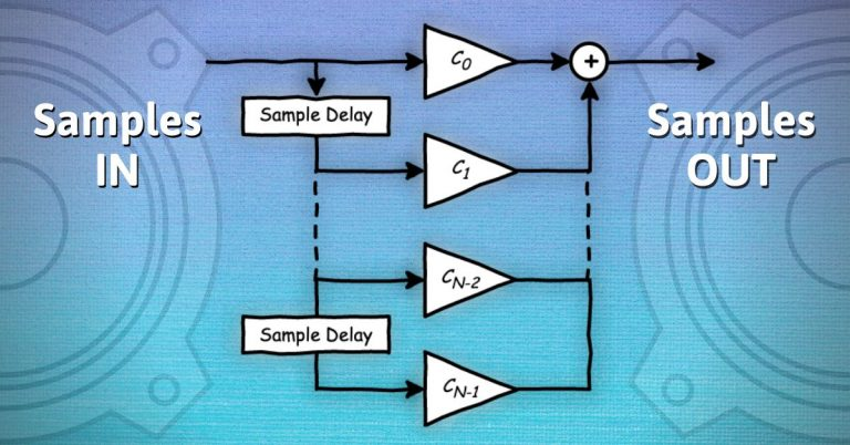
Figure 6 shows a Butterworth 1st order low-pass filter with a cut-off frequency of 1 kHz (fs = 48 kHz). The important thing to note is that a portion of the previous sample is fed back, or re-circulated, into the filter.

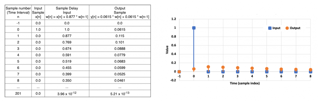
Now let’s calculate the impulse response using Figure 7. For this filter, the impulse response starts with a value of 0.0615 and, even though subsequent input samples are 0, the output of the filter decays but continues with non-zero values essentially forever. Since the output of the filter goes on for infinite time, the filter is called an infinite impulse response or IIR filter.
The thicker blue line in Figure 8 shows the frequency response of the low-pass filter. The thinner blue line above shows the response of a 1st order high-pass Butterworth filter with a cut-off frequency of 1 kHz (fs = 48 kHz).
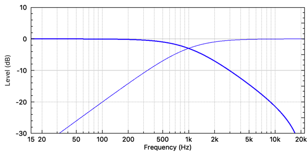
Figure 9 depicts the signal flow and coefficients for the high-pass filter.
Filter order. For a digital filter, the filter order is the maximum amount of sample delay used in the digital filter. For IIR low-pass and high-pass filters, the frequency response roll-off is 6 dB per octave multiplied by the order. (For example, a 3rd order high-pass filter has an 18 dB/octave roll-off.)

The FIR Filter
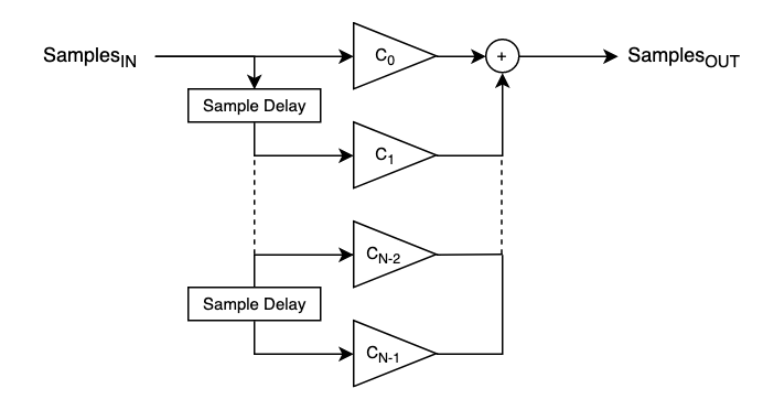
Figure 10 shows the signal flow for a general FIR filter. The coefficients (C0 to CN-1) are the “taps” and so for a N-length FIR filter there are N taps and N-1 sample delay elements. The filter order is N-1.
While a short FIR filter can’t do very much, longer FIR filters become quite powerful by essentially blending a long history of audio samples to cause level and phase changes at different frequencies in controlled ways.
The IIR Biquad
The second order IIR filter is typically called the biquad filter. (Figure 11 offers the Direct Form 2 version.)

Biquads form the basis of most IIR filtering in digital signal processors. Shelf, parametric and all-pass filters can be implemented in this form, and high-pass and low-pass filters of any order are usually implemented as a cascade of connected biquad filters. A 1st order filter can be implemented in the biquad by setting coefficients a2 and b2 to 0.0. Setting coefficients a1 and a2 to 0.0 turns the biquad into a 3-tap FIR filter.