Isolator Mounted Equipment Rails
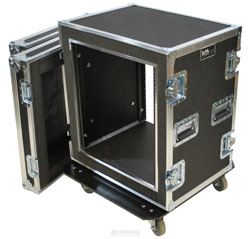
A third and less common type of shock absorbing rack suitable for light equipment, such as signal processing equipment, is constructed by mounting the front and rear equipment mounting rails to the side of a protective rack with rubber or spring isolators.
Once the isolator has been properly chosen based on the load it will carry, the inside dimensions of the rack can be determined so that the equipment rails will sit 17.75 inches (450.9 mm) apart. These racks are difficult to custom manufacture and are best purchased as a complete unit from one of the manufacturers specializing in this style of rack.
Shock Damage And Its Prediction
Shock damage to equipment is caused by acceleration forces developed during impact. Shock is measured in gs, one g being equal to the force of gravity. The shock which results during impact is determined by the speed prior to impact and the time taken to come to a stop or the shock rise time.
The shock rise time will depend on the elasticity of the striking body, the resilience of the impact surface, and the size of the contact area and its shape. The stopping time and the G forces are directly proportional.
For an object dropped from a given height, the G forces are predicted by the formula:
G = √b x 72/t
Where
G = acceleration in gs
b = drop height in inches
t = shock rise time in milliseconds
A rigid load dropped 36 inches (0.91 m) to a concrete floor will experience over 200g while a 4-inch (101 mm) fall to sand will develop about 30g. Anything that can be done to mount sensitive equipment resiliently inside equipment cases is worthwhile.

Rack Layouts
In preparing rack layouts the designer may wish to consider the following guidelines:
1. Locate heavy items such as power supplies and amplifiers near the bottom for ease of installation and removal.
2. Locate items which receive a lot of operator attention, such as jackfields or signal processing, between the waist and eye level of the operator when he or she is in normal operating position.
3. Group together pieces of equipment which are related; for example, the paging and communications equipment in one rack, the switching and distribution equipment in another, and the effects and signal processing equipment in yet another, and so on.
4. Separate, when possible, signal equipment of different levels and types:
—Microphone level equipment
—RF (wireless microphone) equipment
—Line level equipment
—Control and power supply equipment
—Loudspeaker level equipment
—Video equipment
—Computer equipment

5. Leave space around equipment which is known to run hot—at least 1 rack unit above and below. Consider using a baffled vent panel above these units.
6. Avoid putting anything with controls on the front panels at the very bottom of the rack where they can be hit (with feet or brooms, for example).
7. Some amplifiers create strong electromagnetic fields around themselves, and sensitive equipment can have hum induced into its circuits if located immediately above or below. A spacing of 2 rack units (2RU) is often sufficient.
8. Power amplifier racks that contain amplifiers which do not move air in or out of the rack, such as convection and side-to-side fan types, should have forced air cooling.
9. Racks which have many items mounted on the rear rails deserve special attention, as this can restrict access to the rear of the front-mounted equipment, making wiring and service difficult. More racks may be required to reduce the density.
In practice one finds that in trying to meet all the above goals, conflicts will arise; for example, should all the signal processing for all the loudspeaker systems be together, or should the individual processing be located near the amplifiers they are driving, where it would form a logical grouping? The creative designer must ponder the advantages of the different approaches and may decide that, because the wiring is so much simpler one way than the other, the answer is clear!
Philip Giddings, P.Eng., is the founder of design consultants Engineering Harmonics. With offices in Toronto, Vancouver, and Ottawa, the firm is a world leader in the design of performance sound, video, and communications systems for performing arts centers, sports facilities, public buildings, and houses of worship. He remains a senior consultant to the firm.
Editor’s Note: This article is excerpted from the much-lauded Audio System Designs and Installation by Philip Giddings. It’s now available in trade paperback (xxvi + 574 pp, index, ISBN 978-0-9920244-0-6) exclusively online from the publisher, Post Toronto Books, http://posttoronto.com/.