
To determine the input impedance of a device, both the voltage across the device and the current flowing into the device must be known.
The impedance is simply the voltage across the device E, divided by the current flowing into it, I.
This is given by the following equation:
![]()
It should be understood that since the voltage, E, and the current, I, are complex quantities the impedance, Z, is also complex. That is to say impedance has a magnitude and an angle associated with it.
When measuring loudspeaker input impedance it is common today for many measurements to be made a relatively low drive levels. This is necessitated because of the method employed in the schematic of Figure 1.
In this setup a relatively high value resistor, say 1 Kohm, is used for Rs. As seen from the input of the DUT, it is being driven by a high impedance constant current source. Had it been connected directly to the amplifier/measurement system output it would in all likelihood, be driven by a low impedance constant voltage source.

In both of these cases constant refers to there being no change in the driving quantity (either voltage or current) as a function of frequency or load.
When Rs is much larger than the impedance of the DDT, the current in the circuit is determined only by Rs. If the voltage at the output of the amplifier, Va, is known this current is easily calculated with the following equation and is constant.
![]()
Now that we know the current flowing in the circuit, all we need to do is measure the voltage across the DUT and we can calculate its input impedance. There is nothing wrong with this method. It is limited, as previously mentioned, however, in that the drive level exciting the DUT will not be very large due to the large value of Rs.
For some applications this may be problematic. Loudspeakers are seldom used at the low drive levels to which we are limited using the above method. It may be advantageous to be able to measure the input impedance at drive levels closer to those used in actual operation.
If the current in the circuit can be measured rather than having to be assumed constant this limitation can be avoided. Using a measurement system with at least two inputs, as shown in Figure 2, can do just that.

In this case Rs is made relatively small, say 1 ohm or less. This is called a current sensing resistor. It may also be referred to as a current shunt. Technically this is incorrect for this application, because a current shunt is always in parallel with a component from which current is diverted.
The voltage drop across Rs is measured by input #2 of the measurement system. The current in circuit is then calculated using equation:
![]()
The voltage across the DDT is measured by input #1 of the measurement system. We now know both the voltage across and the current flowing into the DUT so it’s input impedance can be calculated.
I used EASERA for the measurements. It has facilities for performing all of these calculations as should most dual channel FFT measurement systems.
Referencing Figure 2, channel #1 across the DDT should be set as the measurement channel while channel #2 should be set as the reference channel. Dual channel FFT systems divide the measurement channel by the reference channel, so we have:
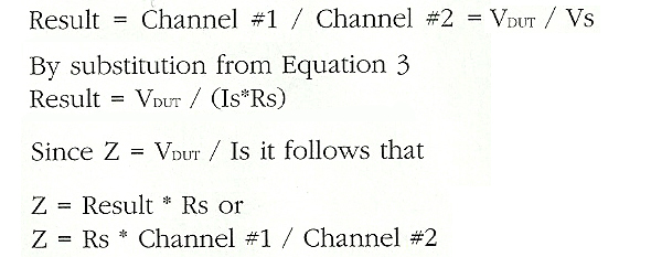
All we have to do it multiply our dual channel FFT measurement by the value of Rs used and we get the correct value for impedance. If Rs is chosen to be 1.0 ohm this becomes really easy.


Ghost In The Machine: Phantom Power
Clearing up the mysteries about phantom power – what exactly is it, and how do we apply it effectively?

The Buck Stops Here: Who’s Responsible For The Overall Success Of Your Integration Project?
Project ownership is a philosophy, an attitude, an ability and willingness to oversee all aspect of a project, and accept the “buck” when it ...read more →

FOH First Aid Kit: Being Prepared For Anything As The Summer Concert Season Rolls In
That beautiful, pristine sound check that happened several hours ago can become a distant memory when the elements take over...

Church Sound: The Power (And Value) Of The Unseen In Worship Tech
Excelling at the invisible side of what we do is one of the biggest ways we can build quality on the visible side.
Lost In Translation? Pro Audio Has A Language All Its Own
Beyond terms and jargon, there is a form of communication based on our passion for the craft.

Helping Build The Future: The Wide-Ranging Educational & Development Efforts Of Tech 25
Inside the work of a Pittsburgh-based non-profit collective network of industry professionals providing production education, workforce programs, hands-on experience and more to the next ...read more →

Three Days In March: A Very Long 72 Hours Battling “Gremlins” At The 1984 Juno Awards
The “normal” amount of time to mount and broadcast the show was about a week to 10 days, but the “actual” amount of time ...read more →

Worthwhile Endeavor? The Case For Deploying Plugins At Corporate Events
Viewpoints from numerous mix engineers who are doing high-profile corporate shows and utilizing external plugins, including some who have been using them for many ...read more →

Tech Focus: Introducing The Lily P4D Microphone Ducking System
Inside a new tool for eliminating microphone bleed in live performances via a simple analog design that's controlled by the artists on stage.

Tandem Touring: Mixing Monitors As A Dual-Engineer Team
In a realm where we engineers are normally the maestro of our own domain, we will be sharing leadership of the department with another ...read more →

In The Studio: Organizing Your Session Files
Some tips to help keep things running smoothly when the track count starts to climb and the chaos starts to ensue...

Sonic Illusions: Creating “Mood” In Recording Mixes
Working to build the "sonic illusions" that help take a song to the next level...