

For those who haven’t studied electronics, it may come as a shock (pun intended) that all sound equipment runs on DC power. But wait a minute, you say – I plug my gear into AC power sources!
Inside every imaginable piece of audio gear is an AC-to-DC convertor known as the power supply. If the various semi-conductors (transistors, op-amps, DSP chips, FPGA chips, etc.) were to be supplied with 50 or 60 Hz AC power, the modulation effect would make them unusable for audio applications. Hmmm. (Or is that “Hummm”?)
So why do we use AC if we ultimately require DC to run our equipment? Simple: AC voltage can be easily stepped-up or stepped down, whereas DC cannot. AC generates a magnetic field that permits the voltage of an AC power system to be altered by means of a power transformer. This is essential in designing long-distance power transmission systems (and even short-distance ones).
The voltage of the transmission lines coming from a major power source is very high – as much as 765,000 volts AC – in order to minimize the size of the conductors and the resistive loss over distance. If the voltage was low, such as what we use in our homes and buildings, the transmission lines would need to be as large as huge storm pipes – and even then, the practical distance for power transmission would be quite short and the cost of the copper wire would be, well… astronomical.
A basic rule of electric power is that as the voltage increases, the required conductor size decreases, for a given value of power transfer. Because AC power can be stepped-up in voltage for long distance runs, and then stepped down for safe usage in our audio gear, lighting equipment, and our homes, it’s the only practical way to move a lot of power from point A to point B.
Let’s take a look at the reasons why AC is well suited to this task and how our work with audio benefit from a solid understanding of how AC power works.
Three For Balance
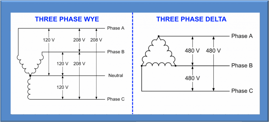
All power distribution from any large generator plant (hydro, coal, nuclear, wind) starts out as 3-phase power (3Ø). Each “leg” of the 3-phase system presents the identical voltage potential as the other two legs, but each is 120 degrees apart from the others in phase. Power generators throughout the world are designed and built with three sets of coils, physically aligned 120 degrees apart, in order to balance their rotating shafts (called rotors) that are subject to immense torque loads.
On the receiving end, the large motors that pump water into our cities and waste products out of them, raise and lower elevators, run industrial machinery, and perform a zillion other tasks, are also 3-phase for the same reason: they are balanced better under high torque loads.
But it gets a bit more complicated: there’s also a neutral. The neutral conductor provides a reference that can be used to allow any one of the three phase “legs” to provide single-phase power to devices such as amplifiers, signal processors, consoles, and other gear that we utilize in our work.
Nonetheless, 3-phase power should be understood as it applies to audio usage. First, the load presented to each of the three phase legs of the 3Ø power distribution system should be balanced as closely as possible. This can be difficult to accomplish in an audio system. At the time of this writing, there are no known amplifiers that are designed to operate directly on 3-phase power.
Therefore, each of the three legs will be broken out and referenced to neutral in order to power the sound system. Or, in some cases, two legs of a 3-phase power system can be used to power amplifiers at 208 or 240 volts AC, if the amplifier(s) can accept those voltages (this statement relates to North American power as opposed to power in Europe, where 230 volts AC at 50 Hz is the norm for a single leg). It’s a good idea to provide amplifiers with 208 or 240 volts AC if you can because the power transfer is always better at higher voltages (as long as the amplifier is built to handle it).
I’m mentioning amplifiers here because they’re the devices that consume the lion’s share of power in any large system. Consoles, wireless systems, outboard and backline gear, and so on, may need 50 amperes – maybe 100 or even 150 amperes – but a large concert system might need several thousand amperes of power at 120 volts AC.
Pressure & Volume
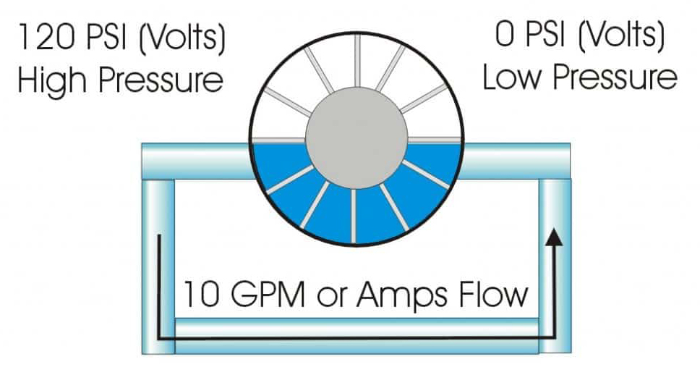
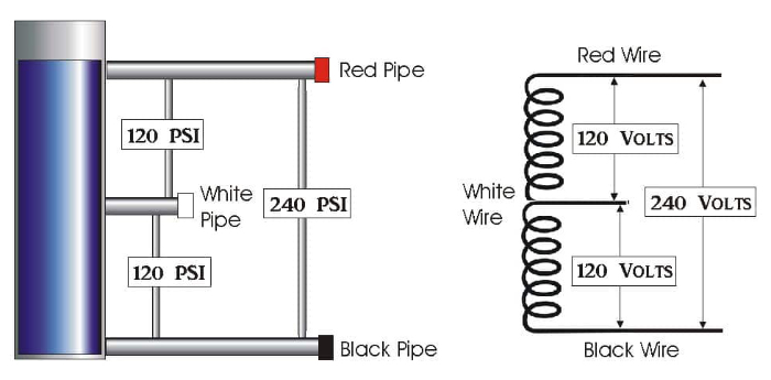
Power is power. There is no shortcut. Ohm’s Law states that 1 volt x 1 amp = 1 watt. Or perhaps more relevant, 120 volts x 10 amperes = 1,200 watts – about the rating of a moderate-sized pro audio power amplifier. Electric power is hard to visualize, so most college courses use the water analogy because we all know what water looks like and can more easily understand how it behaves than the abstraction of trying to visualize electricity.
Voltage is like water pressure. The more pressure, the further the water will travel from its source. Amperage is like water volume. The more volume, the more amount of water is able to move from one place to another, in a given period of time. Power is the integration of voltage and amperage, i.e., water pressure and water volume. (Niagara Falls has plenty of both.)
When you have lots of volts but little amperage, you’ve got the makings of a good way to power a spark plug. Conversely, if you have lots of amps but little voltage, you’ve got something like a car battery, which is why we have ignition coils – to increase the 12-volt battery to the thousands of volts that make the spark plug “spark.”
Now, if you have lots of both volts and amps, you’ve got the ingredients for a power grid and had better be careful about getting too close to it. Anything in the vicinity of 440 or 480 volts is considered very dangerous and in the real world can be truly life threatening (though make no mistake; even a modest 120-volt system can be deadly under the right circumstances). Further, anything over 600 volts must be labeled “high voltage” according to the NEC (National Electrical Code). It can kill in an instant.
Setting It Up
How does all this apply to sound? The dangers of large-scale electrical power means that caution should be exercised as you balance your load in respect to the power source. Don’t circuit all subwoofer/LF amps on one leg of a 3-phase power source, then put the smaller mid-range amps on another leg, and the smallest HF amps on the third leg – tempting though this might be.
Instead, balance the sub/LF amps on all three legs, then do the same thing for MF and HF. For example, if a sound system has 48 amplifiers for LF, which will almost always draw the most power under typical conditions, they should be circuited so that 16 are on each leg. Assuming the system also has 36 MF amplifiers, put 12 on each leg. Further assuming 24 HF amps, put eight on each leg. You get the picture.
This becomes even more important when the number of amplifiers grows to something like 96, 48, and 24, or perhaps double or triple that for large-scale concert systems. With today’s modern amplifiers, such numbers can equate to very serious power demands.
Extend the process of load balancing to stage monitor amplifiers, mixers (large consoles can draw substantial power), signal processing, and all other electrical loads that fall in your domain. A balanced system will also be far less likely to avoid problems such as early amplifier clipping, tripped circuit breakers, and ground loops that will cause hum and buzz.
Chasing The Loops
What exactly is a neutral conductor? As previously noted, neutral is a conductor that allows each leg of the 3-phase, 208-volt power source to provide 120 volts AC when one or more legs are referenced to neutral. In most modern buildings neutral is tied to ground (earth) at the electrical service entrance.
That said, there are sometimes exceptions. In systems known as Clean Technical Ground, the neutral refers back to a point upstream of the power source that will always be electrically tied to the true earth ground, but the connection might be some distance away. A Clean Technical Ground references all ground connections to a true earth ground that’s as close as possible to where the equipment is being used to keep the impedance of the ground connection as low as possible – along with keeping noise as low as possible.
The ground conductors are normally configured in a star configuration. That is, each major load has a ground conductor that’s brought back to the actual ground rod separately, as opposed to being daisy-chained together.
I once assembled a temporary 48-track ADAT recording studio in a large house in Lake Tahoe. All attempts to chase out the ground loops and quiet down the system proved to be futile. The cure was to visit Ace Hardware, buy an 8-foot steel ground rod, and spend the afternoon pounding it into the earth.
I then ran a #2-gauge wire from the ground rod to the studio room, lifted all the house grounds with ground-lift adapters, and connected the new ground wire to about 18 multi-outlet AC strips by means of plugging-in a U-ground connector into an outlet on each strip that was directly connected to the ground rod. A bit unorthodox, but it cleaned up the system, with no discernible hum or buzz on the final product.
You can do this something like this in temporary concert situations, but even easier if you’re prepared for it. Depending on the magnitude of power that’s needed, it might mean pounding a single 8-foot-long, 3/4-inch-diameter rod into the ground, and connecting it to your power distribution system (PD) instead of connecting it to the building ground.
In order to comply with the NEC, a grounding rod cannot be used as the only ground path for an electrical system that’s tied into the power grid. While this is perfectly acceptable for a generator at a concert, that’s because you’re creating a separately derived system that has the generator completely floating with respect to the power grid.
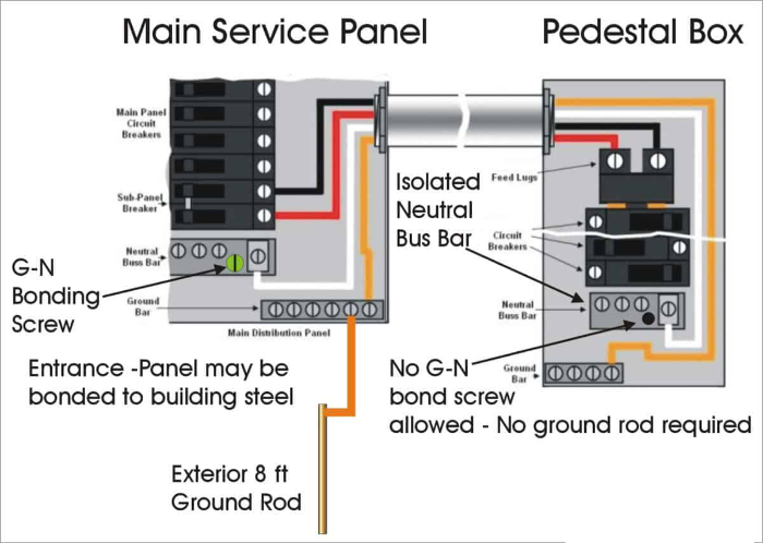
However, when you’re plugged into any sort of AC outlet that’s connected to the power grid, there should be what’s called the neutral/ground bond in the incoming service panel. The Bonding Point is what provides a return path for fault current in the event that there’s a short circuit to the chassis in a piece of sound gear.
Because a grounding rod is a fairly poor conductor to earth ground (perhaps 25 to 100 ohms), a short circuit current will only create a few amperes of fault current, which is not enough to trip the branch circuit breaker. This can result in every instrument, amplifier and microphone plugged into this unbonded branch circuit developing up to 120 volts AC on its metal parts. In other words, if you touch anything that’s grounded while holding onto your guitar strings or getting your lips on the mic, it can be deadly.
So, in our example of the star grounding connection, you’ll want to add one more conductor from the center of the star back to the service panel ground/bonding point as close to the neutral bond as possible. This will provide the best of both worlds – a quiet ground for the sound system along with safely grounded electrical power for the musicians.
Hot & Neutral
Why are some power systems called “single phase” when there seems to be two “hots” and a neutral? This can be confusing. The presence of two energized “hot” poles and a neutral conductor are commonly seen in a typical household residence. They would seem to imply that the system is 2-phase.
However, it’s not. Only one leg of the 3-phase distribution provided by the power company is brought to each household, and then a local transformer that might serve one, two or three houses provides the 240-volt power for appliances.
In such cases, the transformer has a center-tap that becomes the neutral reference that derives the 120 volts AC for all the non-240-volt household usages. The center tap must be tied to an earth ground to prevent potentially lethal conditions if something goes wrong with the appliances that are being powered from this single-phase source.
Diverting Energy
AC ground is both incredibly simple yet highly elusive when it comes to managing hum and buzz problems. In its humble beginnings, a ground connection simply provided a means of diverting electrical energy to a literal connection to earth, to avoid electrical shock. Later, in power transmission systems, the use of earth-ground, instead of an additional neutral conductor, eliminated the need to run a fourth wire, thereby saving a lot of money in long distance transmission applications.
In the world of pro audio, we experience all sorts of trouble related to grounding – hums, buzzes, and sometimes even mild electrical shock. The first rule is never to lift or eliminate the ground connection. (Never means NEVER.) If it’s lifted in one place, it darn well better be re-attached in another place – and in a manner that cannot be accidentally detached. This is why all modern electrical wiring devices (i.e., plug and receptacle connectors) are designed to “make” the ground connection first, and “break” the ground connection last.
Instead, work out the grounding issues in other ways. Ground loops are often the sum of numerous problems. Disconnecting a signal ground is not a recommended practice, but it’s far safer than disconnecting an AC power ground. Audio isolation transformers on the signal side of the world usually solve ground problems. There are also isolation transformers available from companies that actually pay attention to our small industry, such as Furman.
Keeping It Together
There are ways to mitigate, or at least reduce, the issues that cause ground-related noise. It starts with basic maintenance.
Periodically tighten all connections in your power distro equipment. Copper wire “flows” under the force of a pressure connection, which in time can cause the resistance in the connection to increase as the pressure on the wires becomes looser and looser.
Regularly check the condition of your wiring devices. Twist locks, pin-and-sleeve stage connectors, U-ground plugs and receptacles, can all easily wear-out when subjected to constant usage, especially under inclement conditions. Male connectors can usually be restored by burnishing the contact points with a non-residual contact burnisher, but the female receptacles cannot be as easily renewed. It’s usually better to replace them if possible.
But the industry standard is DeoxIT contact cleaner which is great at removing stubborn oxidation while creating a barrier to help prevent further corrosion due to dampness. It’s simply the best, and you only need a small spritz to clean and protect any electrical contacts.
Finally, there’s the design of the system itself. I see many sound rental companies use the same power panels that are intended for residential power distribution, readily available at Home Depot, Lowes, etc. However, note that these type of panels, and the cheap thermal/magnetic circuit breakers that they’re designed to be used with, are not really suited for daily use on the road.
A better approach that will last a lot longer and provide far less headaches is a power distribution system from a supplier that has spent years planning, designing, and manufacturing road-worthy PD systems intended for the sound and production industry. These include features such as the correct choice of connectors, magnetic-hydraulic circuit breakers (instead of thermal breakers which can nuisance trip in high ambient temperatures), rugged chassis designs, internal neutral and ground buses that are of very low impedance, integrated voltage and amperage meters, and in some cases much more.
Power is one of those topics that’s both simple and complex at the same time. On the one hand, a power distro plan can be drawn on a napkin — 100 amps in, three 30-amp connectors out. On the other hand, the choice of proper components, build quality, and the attention to critical details is what separates a shoddy, trouble-plagued PD from one that will silently give many years of safe, reliable service.


